Information injection-pump assembly
ZEXEL
104303-2380
1043032380
ISEKI
62156000080
62156000080
Rating:
Service parts 104303-2380 INJECTION-PUMP ASSEMBLY:
1.
_
3.
GOVERNOR
4.
SUPPLY PUMP
5.
AUTOM. ADVANCE MECHANIS
6.
COUPLING PLATE
7.
COUPLING PLATE
8.
_
9.
_
11.
Nozzle and Holder
6515300-1100E
12.
Open Pre:MPa(Kqf/cm2)
11.8{120}

15.
NOZZLE SET
Include in #1:
104303-2380
as INJECTION-PUMP ASSEMBLY
Cross reference number
ZEXEL
104303-2380
1043032380
ISEKI
62156000080
62156000080
Zexel num
Bosch num
Firm num
Name
104303-2380
62156000080 ISEKI
INJECTION-PUMP ASSEMBLY
E3AF1 * K
E3AF1 * K
Calibration Data:
Adjustment conditions
Test oil
1404 Test oil ISO4113 or {SAEJ967d}
1404 Test oil ISO4113 or {SAEJ967d}
Test oil temperature
degC
40
40
45
Nozzle and nozzle holder
105780-8140
Bosch type code
EF8511/9A
Nozzle
105780-0000
Bosch type code
DN12SD12T
Nozzle holder
105780-2080
Bosch type code
EF8511/9
Opening pressure
MPa
17.2
Opening pressure
kgf/cm2
175
Injection pipe
Outer diameter - inner diameter - length (mm) mm 6-2-600
Outer diameter - inner diameter - length (mm) mm 6-2-600
Tester oil delivery pressure
kPa
157
157
157
Tester oil delivery pressure
kgf/cm2
1.6
1.6
1.6
Direction of rotation (viewed from drive side)
Right R
Right R
Injection timing adjustment
Direction of rotation (viewed from drive side)
Right R
Right R
Injection order
1-3-2
Pre-stroke
mm
2.1
2.05
2.15
Beginning of injection position
Drive side NO.1
Drive side NO.1
Difference between angles 1
Cal 1-3 deg. 120 119.5 120.5
Cal 1-3 deg. 120 119.5 120.5
Difference between angles 2
Cyl.1-2 deg. 240 239.5 240.5
Cyl.1-2 deg. 240 239.5 240.5
Injection quantity adjustment
Adjusting point
A
Rack position
10.5
Pump speed
r/min
700
700
700
Average injection quantity
mm3/st.
28.4
27.4
29.4
Max. variation between cylinders
%
0
-2.5
2.5
Basic
*
Fixing the lever
*
Injection quantity adjustment_02
Adjusting point
B
Rack position
7.1+-0.5
Pump speed
r/min
425
425
425
Average injection quantity
mm3/st.
6.5
5.5
7.5
Max. variation between cylinders
%
0
-14
14
Fixing the lever
*
Remarks
Adjust only variation between cylinders; adjust governor according to governor specifications.
Adjust only variation between cylinders; adjust governor according to governor specifications.
Injection quantity adjustment_03
Adjusting point
C
Rack position
13+1
Pump speed
r/min
100
100
100
Average injection quantity
mm3/st.
37
37
Fixing the lever
*
Test data Ex:
Governor adjustment
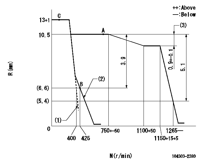
N:Pump speed
R:Rack position (mm)
(1)Set the idle spring.
(2)Main spring setting
(3)Rack difference between N = N1 and N = N2
----------
N1=1150r/min N2=700r/min
----------
----------
N1=1150r/min N2=700r/min
----------
Speed control lever angle
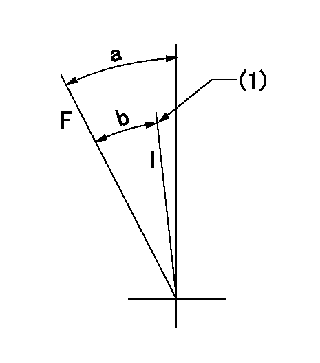
F:Full speed
I:Idle
(1)Stopper bolt setting
----------
----------
a=36deg+-3deg b=30deg+-6deg
----------
----------
a=36deg+-3deg b=30deg+-6deg
Stop lever angle

N:Pump normal
S:Stop the pump.
----------
----------
a=18deg+-5deg b=(38deg)
----------
----------
a=18deg+-5deg b=(38deg)
Timing setting

(1)Pump vertical direction
(2)Position of gear mark '00' at No 1 cylinder's beginning of injection
(3)B.T.D.C.: aa
(4)-
----------
aa=18deg
----------
a=(110deg)
----------
aa=18deg
----------
a=(110deg)
Information:
start by:a) remove fuel injection lines**This operation location is in the ENGINE DISASSEMBLY AND ASSEMBLY section. 1. Disconnect the fuel lines from fuel transfer pump (4) and fuel manifold (3). Disconnect fuel line (2) from the fitting. Disconnect the fuel return line to the tank at (1). Install plugs or caps on all fuel line openings.2. Disconnect drain line (5) from the governor housing. Move the fuel lines and drain line clear of the fuel injection pump housing and governor. 3. Remove bolts (6) that hold the oil manifold to the governor housing. 4. Remove cover (7) from the timing gear cover.5. Remove the bolt and washer that hold the timing gear to the camshaft in the fuel injection pump housing. 6. Install tooling (A) and loosen the timing gear on the camshaft in the fuel injection pump housing.7. Fasten a strap and hoist to the fuel injection pump housing and governor as shown. 8. Remove three nuts (8) and remove the fuel injection pump housing and governor. Weight is 25 kg (56 lb.).Install Fuel Injection Pump Housing And Governor
1. Be sure O-ring seals (1) and (2) are in position on the fuel injection pump housing and governor and put clean oil on the O-ring seals.2. Remove the cover on the fuel injection pump housing and install timing pin (A). Turn the camshaft until timing pin (A) goes in the groove in the camshaft as shown. 3. Fasten a strap and hoist to the fuel injection pump housing and governor and put in position on the timing gear plate and oil manifold (3). Install the three nuts that hold the fuel injection pump housing to the timing gear plate and the two bolts that hold the governor housing to oil manifold (3).
After the fuel injection pump housing and governor are installed on the timing gear plate be sure the rack is free to move. The O-ring seal on the drive end of the fuel injection pump can hold the rack and prevent free movement of the rack. If the rack does not move freely remove the fuel injection pump housing and governor and check the O-ring seal on the drive end of the fuel injection pump housing.
4. Install the bolt and washer (4) as shown to hold the timing gear to the camshaft. Install washer (4) with the larger outside diameter toward the bolt head. Tighten the bolt finger tight only.5. Use the following procedure to put the No. 1 piston at top center on the compression stroke. No. 1 piston at top center (TC) on the compression stroke is the starting point for all timing procedures. The engine is seen from the flywheel end when direction of flywheel rotation is given. Do not turn the flywheel backward. a) Remove plug (5) from the flywheel housing and the breather from the valve cover.b) Turn the flywheel counterclockwise until a 3/8"-16 NC bolt (6) at least 2.5 in. long can be installed in the flywheel through the hole in
Have questions with 104303-2380?
Group cross 104303-2380 ZEXEL
Isuzu
Iseki
104303-2380
62156000080
INJECTION-PUMP ASSEMBLY
E3AF1
E3AF1