Information injection-pump assembly
ZEXEL
104303-2360
1043032360
ISEKI
62156000060
62156000060
Rating:
Service parts 104303-2360 INJECTION-PUMP ASSEMBLY:
1.
_
3.
GOVERNOR
4.
SUPPLY PUMP
5.
AUTOM. ADVANCE MECHANIS
6.
COUPLING PLATE
7.
COUPLING PLATE
8.
_
9.
_
11.
Nozzle and Holder
6515300-1100E
12.
Open Pre:MPa(Kqf/cm2)
11.8{120}

15.
NOZZLE SET
Include in #1:
104303-2360
as INJECTION-PUMP ASSEMBLY
Cross reference number
ZEXEL
104303-2360
1043032360
ISEKI
62156000060
62156000060
Zexel num
Bosch num
Firm num
Name
104303-2360
62156000060 ISEKI
INJECTION-PUMP ASSEMBLY
E3AF1 * K
E3AF1 * K
Calibration Data:
Adjustment conditions
Test oil
1404 Test oil ISO4113 or {SAEJ967d}
1404 Test oil ISO4113 or {SAEJ967d}
Test oil temperature
degC
40
40
45
Nozzle and nozzle holder
105780-8140
Bosch type code
EF8511/9A
Nozzle
105780-0000
Bosch type code
DN12SD12T
Nozzle holder
105780-2080
Bosch type code
EF8511/9
Opening pressure
MPa
17.2
Opening pressure
kgf/cm2
175
Injection pipe
Outer diameter - inner diameter - length (mm) mm 6-2-600
Outer diameter - inner diameter - length (mm) mm 6-2-600
Tester oil delivery pressure
kPa
157
157
157
Tester oil delivery pressure
kgf/cm2
1.6
1.6
1.6
Direction of rotation (viewed from drive side)
Right R
Right R
Injection timing adjustment
Direction of rotation (viewed from drive side)
Right R
Right R
Injection order
1-3-2
Pre-stroke
mm
2.1
2.05
2.15
Beginning of injection position
Drive side NO.1
Drive side NO.1
Difference between angles 1
Cal 1-3 deg. 120 119.5 120.5
Cal 1-3 deg. 120 119.5 120.5
Difference between angles 2
Cyl.1-2 deg. 240 239.5 240.5
Cyl.1-2 deg. 240 239.5 240.5
Injection quantity adjustment
Adjusting point
A
Rack position
9.7
Pump speed
r/min
700
700
700
Average injection quantity
mm3/st.
24.6
23.6
25.6
Max. variation between cylinders
%
0
-2.5
2.5
Basic
*
Fixing the lever
*
Injection quantity adjustment_02
Adjusting point
B
Rack position
7.1+-0.5
Pump speed
r/min
425
425
425
Average injection quantity
mm3/st.
6.5
5.5
7.5
Max. variation between cylinders
%
0
-14
14
Fixing the lever
*
Remarks
Adjust only variation between cylinders; adjust governor according to governor specifications.
Adjust only variation between cylinders; adjust governor according to governor specifications.
Injection quantity adjustment_03
Adjusting point
C
Rack position
13+1
Pump speed
r/min
100
100
100
Average injection quantity
mm3/st.
37
37
Fixing the lever
*
Test data Ex:
Governor adjustment
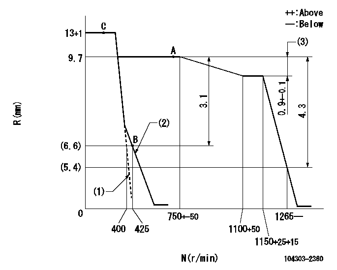
N:Pump speed
R:Rack position (mm)
(1)Set the idle spring.
(2)Main spring setting
(3)Rack difference between N = N1 and N = N2
----------
N1=1150r/min N2=700r/min
----------
----------
N1=1150r/min N2=700r/min
----------
Speed control lever angle
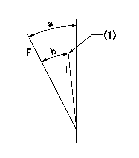
F:Full speed
I:Idle
(1)Stopper bolt setting
----------
----------
a=36deg+-3deg b=30deg+-6deg
----------
----------
a=36deg+-3deg b=30deg+-6deg
Stop lever angle

N:Pump normal
S:Stop the pump.
----------
----------
a=18deg+-5deg b=(38deg)
----------
----------
a=18deg+-5deg b=(38deg)
Timing setting

(1)Pump vertical direction
(2)Position of gear mark '00' at No 1 cylinder's beginning of injection
(3)B.T.D.C.: aa
(4)-
----------
aa=18deg
----------
a=(110deg)
----------
aa=18deg
----------
a=(110deg)
Information:
2. Disconnect the fuel lines from fuel transfer pump (1).3. Remove two bolts (2) and fuel transfer pump (1). 4. Be sure O-ring seal (3) is in position on the fuel transfer pump and put clean oil on the O-ring seal.5. Put the fuel transfer pump in position on the fuel injection pump and install the two bolts that hold it in place.6. Connect the fuel lines to the fuel transfer pump.7. Open the fuel shutoff valve at the fuel tank.Disassemble Fuel Transfer Pump
start by:a) remove fuel transfer pump
Cover (2) is under spring tension.
1. Carefully remove bolts (1) and cover (2) from the fuel transfer pump. 2. Remove spring (3), valve (4) and O-ring seals (5) from the cover. 3. Remove springs (6) and (7) from the pump housing. 4. Remove sleeve (8) from the pump housing. 5. Remove sleeve (12), piston (16), O-ring seal (11) and piston (9) from sleeve (8). Remove plate (15), valve (10) and seal (14) from piston (9). Remove O-ring seal (13) from sleeve (8). 6. Remove O-ring seal (17) from the pump housing. 7. Push guide (18) through the pump housing and remove guides (23) and (18) together. Remove rod (20), guide (23), O-ring seal (19) and tappet (21) from guide (18). Remove ring (22) from tappet (21). 8. Remove connector (24), valve (26) and seal (25) from the pump housing. 9. Remove plug (30), spring (28), valve (29) and seal (27) from the pump housing.Assemble Fuel Transfer Pump
1. Clean all parts and be sure all passage are open. 2. Be sure the O-ring seal is in position on plug (4) and put 4L7464 Silicone Grease on the O-ring seal. Valves (2 and 6) must be installed as shown for the pump to work correctly.3. Install seal (1), valve (2), spring (3) and plug (4) in the pump housing as shown. Tighten plug (4) to a torque of 20 7 N m (15 5 lb.ft.). 4. Be sure the O-ring seal is in position on connector (7) and put 4L7464 Silicone Grease on the O-ring seal.5. Install seal (5), valve (6) and connector (7) in the pump housing as shown. Tighten connector (7) to a torque of 55 10 N m (40 7 lb.ft.). 6. Install the ring on tappet (8). Install tappet (8), O-ring seal (12), guide (9) and rod (10) in guide (11). Put 4L7464 Silicone Grease on O-ring seal (12). Install guides (11) and (9) as a unit in the pump housing as shown. 7. Install O-ring seal (13) in the pump housing and put 4L7464 Silicone Grease on the O-ring seal. 8. Install seal (15), valve (19) and plate (16) in piston (14) as shown. Install piston (14), O-ring seal (17), piston (20) and guide (21) in guide (18) as shown. Install the O-ring seal on guide (18) and put 4L7464 Silicone Grease on O-ring seal (17) and the O-ring seal on guide (18). 9. Install guide (18) in the pump housing as shown.
Have questions with 104303-2360?
Group cross 104303-2360 ZEXEL
Isuzu
Iseki
104303-2360
62156000060
INJECTION-PUMP ASSEMBLY
E3AF1
E3AF1