Information injection-pump assembly
ZEXEL
104303-2240
1043032240
ISEKI
65156012710C
65156012710c
Rating:
Service parts 104303-2240 INJECTION-PUMP ASSEMBLY:
1.
_
3.
GOVERNOR
5.
AUTOM. ADVANCE MECHANIS
6.
COUPLING PLATE
7.
COUPLING PLATE
8.
_
9.
_
11.
Nozzle and Holder
6515300-1100E
12.
Open Pre:MPa(Kqf/cm2)
11.8{120}

15.
NOZZLE SET
Include in #1:
104303-2240
as INJECTION-PUMP ASSEMBLY
Cross reference number
ZEXEL
104303-2240
1043032240
ISEKI
65156012710C
65156012710c
Zexel num
Bosch num
Firm num
Name
104303-2240
65156012710C ISEKI
INJECTION-PUMP ASSEMBLY
E3AE1 * K
E3AE1 * K
Calibration Data:
Adjustment conditions
Test oil
1404 Test oil ISO4113 or {SAEJ967d}
1404 Test oil ISO4113 or {SAEJ967d}
Test oil temperature
degC
40
40
45
Nozzle and nozzle holder
105780-8140
Bosch type code
EF8511/9A
Nozzle
105780-0000
Bosch type code
DN12SD12T
Nozzle holder
105780-2080
Bosch type code
EF8511/9
Opening pressure
MPa
17.2
Opening pressure
kgf/cm2
175
Injection pipe
Outer diameter - inner diameter - length (mm) mm 6-2-600
Outer diameter - inner diameter - length (mm) mm 6-2-600
Tester oil delivery pressure
kPa
157
157
157
Tester oil delivery pressure
kgf/cm2
1.6
1.6
1.6
Direction of rotation (viewed from drive side)
Left L
Left L
Injection timing adjustment
Direction of rotation (viewed from drive side)
Left L
Left L
Injection order
1-3-2
Pre-stroke
mm
2.1
2.05
2.15
Beginning of injection position
Drive side NO.1
Drive side NO.1
Difference between angles 1
Cal 1-3 deg. 120 119.5 120.5
Cal 1-3 deg. 120 119.5 120.5
Difference between angles 2
Cyl.1-2 deg. 240 239.5 240.5
Cyl.1-2 deg. 240 239.5 240.5
Injection quantity adjustment
Adjusting point
A
Rack position
9.1
Pump speed
r/min
1300
1300
1300
Average injection quantity
mm3/st.
28.3
27.3
29.3
Max. variation between cylinders
%
0
-2.5
2.5
Basic
*
Fixing the lever
*
Injection quantity adjustment_02
Adjusting point
B
Rack position
6.4+-0.5
Pump speed
r/min
575
575
575
Average injection quantity
mm3/st.
7.2
6.2
8.2
Max. variation between cylinders
%
0
-14
14
Fixing the lever
*
Injection quantity adjustment_03
Adjusting point
C
Rack position
13+1
Pump speed
r/min
100
100
100
Average injection quantity
mm3/st.
37
37
Fixing the lever
*
Test data Ex:
Governor adjustment
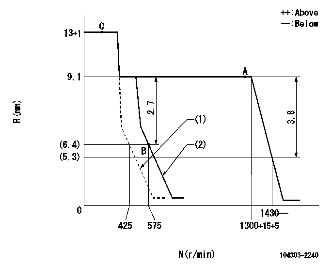
N:Pump speed
R:Rack position (mm)
(1)Set the idle spring.
(2)Main spring setting
----------
----------
----------
----------
Speed control lever angle
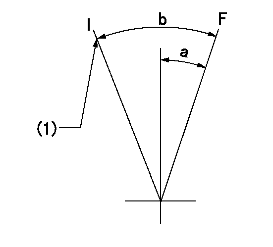
F:Full speed
I:Idle
(1)Stopper bolt setting
----------
----------
a=15deg+-3deg b=30deg+-6deg
----------
----------
a=15deg+-3deg b=30deg+-6deg
Timing setting

(1)Pump vertical direction
(2)Position of gear mark 'Z' at No 1 cylinder's beginning of injection
(3)B.T.D.C.: aa
(4)-
----------
aa=18deg
----------
a=(120deg)
----------
aa=18deg
----------
a=(120deg)
Information:
(1) Thickness of spacer plate ... 9.970 0.025 mm (.3925 .0010 in) Thickness of spacer plate gasket ... 0.208 0.025 mm (.0082 .0010 in) For height of liner over top of spacer plate make reference to Cylinder Liner Projection.(2) Camshaft bearing bore (installed) ... 58.80 0.06 mm (2.315 .002 in) Bore in block for camshaft bearings ... 65.100 0.025 mm (2.5630 .0010 in)(3) Bore in block for main bearings (standard size) ... 96.926 0.013 mm (3.8160 .0005 in) Bore in block for main bearings 0.51 mm (.020 in) oversize ... 97.436 0.013 mm (3.8361 .0005 in)(4) Dimension from center of main bearing bore to top of cylinder block (new) ... 383.515 0.165 mm (15.099 .0065 in)(5) Dimension from center of main bearing bore to bottom of cylinder block (new) 153.99 0.10 mm (6.063 .004 in)(6) Torque for bolts holding bearing caps for main bearings: a. Put 2P2506 Thread Lubricant on threads and washer face.b. Tighten all bolts to ... 41 4 N m (30 3 lb ft)c. Put a mark on each bolt and cap.d. Tighten all bolts from mark ... 90 5° Install bearing caps with the part number toward the front of the engine. Be sure that the mark (number) on the bearing cap next to the bolt hole is in agreement with the mark in the cylinder block.(7) Clearance between main bearing cap and cylinder block ... 0.033 mm (.0013 in) tight to ... 0.043 mm (.0017 in) looseMain bearing cap width ... 165.095 0.020 mm (6.4998 .0008 in)Width of cylinder block for main bearing cap ... 165.100 0.018 mm (6.5000 .0007 in) (8) Piston cooling orifice.
There are holes in the bores for the main bearings, between the cylinders for piston cooling orifices. These holes must have orifices (8) installed.
(9) Distance two dowels extend from the surface of the cylinder block ... 19.8 0.5 mm (.78 .02 in)(10) Distance hollow dowel extends from the surface of the cylinder block ... 16.0 0.5 mm (.63 .02 in)(11) Depth to install two dowels below the surface of the cylinder block (apply Loctite #11358) ... 1.0 0.5 mm (.04 .02 in)(12) Distance dowels extend from the front face of the cylinder block ... 22.4 0.5 mm (.88 .02 in)(13) Distance stud extends from the front face of the cylinder block ... 15.7 0.5 mm (.62 .02 in)(14) Distance two dowels extend from the rear face of the cylinder block ... 12.7 0.5 mm (.50 .02 in)
Have questions with 104303-2240?
Group cross 104303-2240 ZEXEL
Iseki
104303-2240
65156012710C
INJECTION-PUMP ASSEMBLY
E3AE1
E3AE1