Information injection-pump assembly
BOSCH
9 400 616 429
9400616429
ZEXEL
104303-2110
1043032110
ISUZU
5156012050
5156012050
Rating:
Service parts 104303-2110 INJECTION-PUMP ASSEMBLY:
1.
_
3.
GOVERNOR
5.
AUTOM. ADVANCE MECHANIS
6.
COUPLING PLATE
7.
COUPLING PLATE
8.
_
9.
_
11.
Nozzle and Holder
5-15300-110-2
12.
Open Pre:MPa(Kqf/cm2)
11.8{120}

15.
NOZZLE SET
Include in #1:
104303-2110
as INJECTION-PUMP ASSEMBLY
Cross reference number
BOSCH
9 400 616 429
9400616429
ZEXEL
104303-2110
1043032110
ISUZU
5156012050
5156012050
Zexel num
Bosch num
Firm num
Name
104303-2110
9 400 616 429
5156012050 ISUZU
INJECTION-PUMP ASSEMBLY
3AE1 K 14BV INJECTION PUMP ASSY PES3K PE
3AE1 K 14BV INJECTION PUMP ASSY PES3K PE
Calibration Data:
Adjustment conditions
Test oil
1404 Test oil ISO4113 or {SAEJ967d}
1404 Test oil ISO4113 or {SAEJ967d}
Test oil temperature
degC
40
40
45
Nozzle and nozzle holder
105780-8140
Bosch type code
EF8511/9A
Nozzle
105780-0000
Bosch type code
DN12SD12T
Nozzle holder
105780-2080
Bosch type code
EF8511/9
Opening pressure
MPa
17.2
Opening pressure
kgf/cm2
175
Injection pipe
Outer diameter - inner diameter - length (mm) mm 6-2-600
Outer diameter - inner diameter - length (mm) mm 6-2-600
Tester oil delivery pressure
kPa
157
157
157
Tester oil delivery pressure
kgf/cm2
1.6
1.6
1.6
Direction of rotation (viewed from drive side)
Left L
Left L
Injection timing adjustment
Direction of rotation (viewed from drive side)
Left L
Left L
Injection order
1-3-2
Pre-stroke
mm
2.1
2.05
2.15
Beginning of injection position
Drive side NO.1
Drive side NO.1
Difference between angles 1
Cal 1-3 deg. 120 119.5 120.5
Cal 1-3 deg. 120 119.5 120.5
Difference between angles 2
Cyl.1-2 deg. 240 239.5 240.5
Cyl.1-2 deg. 240 239.5 240.5
Injection quantity adjustment
Adjusting point
A
Rack position
7.7
Pump speed
r/min
1400
1400
1400
Average injection quantity
mm3/st.
27.2
26.2
28.2
Max. variation between cylinders
%
0
-2.5
2.5
Basic
*
Fixing the lever
*
Injection quantity adjustment_02
Adjusting point
B
Rack position
6.1+-0.5
Pump speed
r/min
425
425
425
Average injection quantity
mm3/st.
9
8
10
Max. variation between cylinders
%
0
-14
14
Fixing the rack
*
Remarks
Adjust only variation between cylinders; adjust governor according to governor specifications.
Adjust only variation between cylinders; adjust governor according to governor specifications.
Injection quantity adjustment_03
Adjusting point
C
Rack position
13+1
Pump speed
r/min
100
100
100
Average injection quantity
mm3/st.
37
37
Fixing the lever
*
Test data Ex:
Governor adjustment
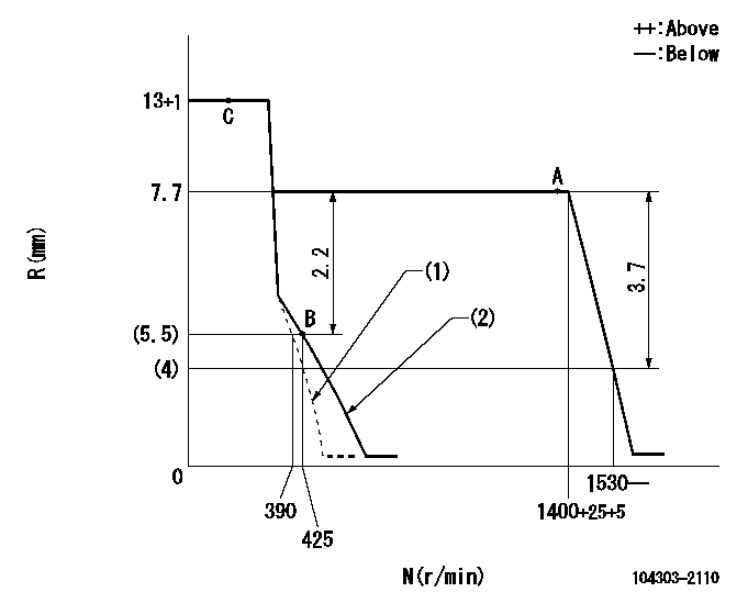
N:Pump speed
R:Rack position (mm)
(1)Set the idle spring.
(2)Main spring setting
----------
----------
----------
----------
Speed control lever angle
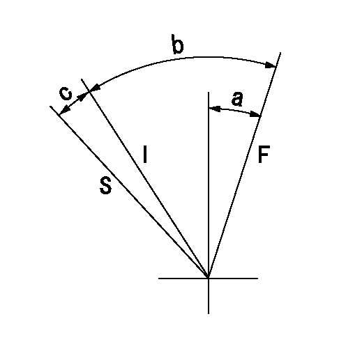
F:Full speed
I:Idle
S:Stop
----------
----------
a=15deg+-5deg b=40deg+-6deg c=10deg+-6deg
----------
----------
a=15deg+-5deg b=40deg+-6deg c=10deg+-6deg
Timing setting

(1)Pump vertical direction
(2)Position of gear mark 'Z' at No 1 cylinder's beginning of injection
(3)-
(4)-
----------
----------
a=(120deg)
----------
----------
a=(120deg)
Information:
Illustration 15: (A) Injector sleeve. (3) Lower pilot. (36) Pipe or tubing.6. Place new injector sleeve (A) into its bore in the cylinder head. Wipe away any excess retaining compound that is either in or above the injector sleeve.7. Install lower pilot (3) into the injector sleeve. To avoid damage to the guide on the lower pilot (3), use a piece of pipe or tubing (36) with a small hammer to LIGHTLY tap the lower pilot. This will ensure that the new injector sleeve is fully seated in the cylinder head.Remove lower pilot (3).
Illustration 16: (14) Roller expander. (32) Mandrel.8. Place a coating of clean engine oil on 4C-6730 Roller Expander (14). Ensure the rollers are completely covered with oil.9. Pull and hold mandrel (32) out of the roller expander (14) as far as possible. Then completely insert the roller expander into the injector sleeve.10. Place a torque wrench with a 11 mm socket on the hex portion of 4C-6730 Roller Expander mandrel. Turn the torque wrench in a clockwise (CW) direction in order to achieve a torque of 11 N m (100 lb in). If torque stops increasing before 11 N m (100 lb in) the sleeve is not hard enough or the bore is oversized in the head.
To ensure that accurate torque is achieved, a calibrated 4C-6936 Torque Wrench or equivalent is required.
11. When the specified torque is reached, stop turning the roller expander in the clockwise (CW) direction. Now turn the roller expander in the counterclockwise (CCW) direction until it is loose in the injector sleeve.Remove 4C-6730 Roller Expander from the injector sleeve.12. Wipe the roller expander, especially the rollers, to remove any traces of 7M-7456 Bearing Mount or Loctite® 609 that may have built up from the injector sleeve. When usage of 4C-6730 Roller Expander is completed, clean it thoroughly using either 1U-8803 Cleaner Concentrate or 8T-9011 Component Cleaner. After the cleaning, place a generous coat of either 1U-8265 Penetrating Oil or 1U-8809 Rust Preventive on the roller expander. Place it in its storage case.
Illustration 17: (A) Injector sleeve. (13) Driver. (15) Guide bushing. Wage/flaring assembly: (8) Set screw. (9) Bottom swage. (11) Flare tool.13. Install 4C-6591 Bottom Swage (9) in 9U-6856 Flare Tool (11) using 4C-5502 Set Screw (8).14. Slide same guide bushing (15) used previously onto 9U-6856 Flare Tool (11).
Some 9U-6856 Flare Tools have their part number stamped on the turn which fits into the guide bushing. This arrangement interferes with the fit. Before the first tool use, the part number should be filed down as necessary in order to permit fit of the flare tool in the guide bushing.
15. Use 5P-3931 Anti-seize Compound, 6V-4876 Molykote Paste Lubricant, or grease to lubricate the swage/flaring assembly. Place it into the sleeve with the flare tool prying notch facing either opening between the valve springs. This will allow access for removal of the swage/flaring assembly.16. Place 9U-6857 Driver (13) on 9U-6856 Flare Tool (11).17. Use a hammer to drive down the swage/flaring assembly until
Have questions with 104303-2110?
Group cross 104303-2110 ZEXEL
Isuzu
104303-2110
9 400 616 429
5156012050
INJECTION-PUMP ASSEMBLY
3AE1
3AE1