Information injection-pump assembly
ZEXEL
104303-2081
1043032081
ISUZU
5156011623
5156011623

Rating:
Service parts 104303-2081 INJECTION-PUMP ASSEMBLY:
1.
_
3.
GOVERNOR
4.
SUPPLY PUMP
5.
AUTOM. ADVANCE MECHANIS
6.
COUPLING PLATE
7.
COUPLING PLATE
8.
_
9.
_
11.
Nozzle and Holder
5-15300-110-2
12.
Open Pre:MPa(Kqf/cm2)
11.8{120}

15.
NOZZLE SET
Include in #1:
104303-2081
as INJECTION-PUMP ASSEMBLY
Cross reference number
ZEXEL
104303-2081
1043032081
ISUZU
5156011623
5156011623
Zexel num
Bosch num
Firm num
Name
104303-2081
5156011623 ISUZU
INJECTION-PUMP ASSEMBLY
3AF1 * K
3AF1 * K
Calibration Data:
Adjustment conditions
Test oil
1404 Test oil ISO4113 or {SAEJ967d}
1404 Test oil ISO4113 or {SAEJ967d}
Test oil temperature
degC
40
40
45
Nozzle and nozzle holder
105780-8140
Bosch type code
EF8511/9A
Nozzle
105780-0000
Bosch type code
DN12SD12T
Nozzle holder
105780-2080
Bosch type code
EF8511/9
Opening pressure
MPa
17.2
Opening pressure
kgf/cm2
175
Injection pipe
Outer diameter - inner diameter - length (mm) mm 6-2-600
Outer diameter - inner diameter - length (mm) mm 6-2-600
Tester oil delivery pressure
kPa
157
157
157
Tester oil delivery pressure
kgf/cm2
1.6
1.6
1.6
Direction of rotation (viewed from drive side)
Right R
Right R
Injection timing adjustment
Direction of rotation (viewed from drive side)
Right R
Right R
Injection order
1-3-2
Pre-stroke
mm
2.1
2.05
2.15
Beginning of injection position
Drive side NO.1
Drive side NO.1
Difference between angles 1
Cal 1-3 deg. 120 119.5 120.5
Cal 1-3 deg. 120 119.5 120.5
Difference between angles 2
Cyl.1-2 deg. 240 239.5 240.5
Cyl.1-2 deg. 240 239.5 240.5
Injection quantity adjustment
Adjusting point
A
Rack position
10.5
Pump speed
r/min
700
700
700
Average injection quantity
mm3/st.
28.4
27.4
29.4
Max. variation between cylinders
%
0
-2.5
2.5
Basic
*
Fixing the lever
*
Injection quantity adjustment_02
Adjusting point
C
Rack position
7.1+-0.5
Pump speed
r/min
425
425
425
Average injection quantity
mm3/st.
6.5
5.5
7.5
Max. variation between cylinders
%
0
-14
14
Fixing the lever
*
Remarks
Adjust only variation between cylinders; adjust governor according to governor specifications.
Adjust only variation between cylinders; adjust governor according to governor specifications.
Injection quantity adjustment_03
Adjusting point
D
Rack position
13+1
Pump speed
r/min
100
100
100
Average injection quantity
mm3/st.
37
37
Fixing the lever
*
Injection quantity adjustment_04
Adjusting point
B
Rack position
9.8+-0.5
Pump speed
r/min
1150
1150
1150
Average injection quantity
mm3/st.
26.8
26.8
26.8
Fixing the lever
*
Test data Ex:
Governor adjustment
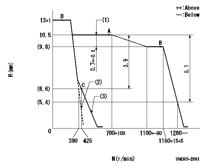
N:Pump speed
R:Rack position (mm)
(1)Rack difference between N = N1 and N = N2
(2)Set the idle spring.
(3)Main spring setting
----------
N1=700r/min N2=1150r/min
----------
----------
N1=700r/min N2=1150r/min
----------
Speed control lever angle
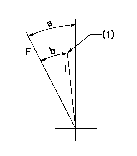
F:Full speed
I:Idle
(1)Stopper bolt setting
----------
----------
a=36deg+-3deg b=26deg+-6deg
----------
----------
a=36deg+-3deg b=26deg+-6deg
Stop lever angle

N:Pump normal
S:Stop the pump.
----------
----------
a=18deg+-5deg b=(38deg)
----------
----------
a=18deg+-5deg b=(38deg)
Timing setting

(1)Pump vertical direction
(2)Position of gear mark '00' at No 1 cylinder's beginning of injection
(3)B.T.D.C.: aa
(4)-
----------
aa=16deg
----------
a=(110deg)
----------
aa=16deg
----------
a=(110deg)
Information:
Introduction
The 7C8966, 7C8972, 8N5651, 8N5887, 9N0495, and 9N5864 Fuel Injection Pump Groups (new), or the 0R0766, 0R0902, 0R0903, 0R2374, and 0R2385 Fuel Injection Pump Group [remanufactured - (reconditioning has been done to a used fuel injection pump and governor group to give the same quality as a new pump group)] are service replacements for the fuel injection pump and governor groups used on 3208 engines, according to the adaptability shown in the chart. These service groups have only those gaskets and seals that are needed to install the fuel injection pump and governor on the engine.Reference: Parts Manual, Service Manual, Engine Information Plate, Fuel Setting Information Microfiche, Fuel System and Related Information MicroficheDo not perform any procedure, outlined in this publication, or order any parts until you read and understand the information contained within.Service Group Chart
Removal and Installation
1. Remove the pump and governor from the engine. Refer to the Service Manual.
When a replacement fuel injection pump and governor is installed on an engine (or when replacement parts are put in a fuel injection pump and governor), use the information on the engine information plate and always check engine low idle speed, set point and the fuel setting dimension. These settings and dimensions must be checked and adjustments made by a mechanic that has the necessary training in fuel system maintenance. Before the fuel system checks and adjustment are made, remove the original factory fuel system seal. After all fuel system work has been completed, install your Dealer seal as a replacement seal. Refer to Fuel System and Related Information or Fuel Setting Information for additional specifications.
2. Put the new service pump group in a 2P8315 Bracket Assembly (1) so it will be easier to work on. Remove the shut-off solenoid and the solenoid ground wire from the old fuel system. Remove the fuel line fittings from the old fuel system. Install these parts in the same location on the new fuel system.3. Locate the engine serial number and write it down. Make reference to the Fuel Setting Information or Fuel System and Related Information to find the part number of the governor high idle spring that is needed for the engine. The same part number governor high idle spring given in the Fuel Setting Information, or the Fuel System and Related Information must be installed in the new service pump group. The 9L6508 High Idle Spring is already installed in the service pump and governor groups. The governor high idle spring needs to be changed only if the needed part number is different than 9L6508. If it is necessary to change the high idle spring, refer to the Service Manual. The part number of the low idle spring is 4N5663 and is the same for all fuel systems.4. A 4N0527 Overfueling Spring is installed in the service pump and governor groups. Refer to the Parts Manual to determine which overfueling spring is required. If the overfueling spring must be changed, refer to the Service Manual for the
Have questions with 104303-2081?
Group cross 104303-2081 ZEXEL
Isuzu
104303-2081
5156011623
INJECTION-PUMP ASSEMBLY
3AF1
3AF1