Information injection-pump assembly
ZEXEL
104303-2080
1043032080
ISUZU
5156011622
5156011622

Rating:
Service parts 104303-2080 INJECTION-PUMP ASSEMBLY:
1.
_
2.
FUEL INJECTION PUMP
3.
GOVERNOR
4.
SUPPLY PUMP
5.
AUTOM. ADVANCE MECHANIS
6.
COUPLING PLATE
7.
COUPLING PLATE
8.
_
9.
_
11.
Nozzle and Holder
5-15300-110-2
12.
Open Pre:MPa(Kqf/cm2)
11.8{120}

15.
NOZZLE SET
Include in #1:
104303-2080
as INJECTION-PUMP ASSEMBLY
Cross reference number
ZEXEL
104303-2080
1043032080
ISUZU
5156011622
5156011622
Zexel num
Bosch num
Firm num
Name
Calibration Data:
Adjustment conditions
Test oil
1404 Test oil ISO4113 or {SAEJ967d}
1404 Test oil ISO4113 or {SAEJ967d}
Test oil temperature
degC
40
40
45
Nozzle and nozzle holder
105780-8140
Bosch type code
EF8511/9A
Nozzle
105780-0000
Bosch type code
DN12SD12T
Nozzle holder
105780-2080
Bosch type code
EF8511/9
Opening pressure
MPa
17.2
Opening pressure
kgf/cm2
175
Injection pipe
Outer diameter - inner diameter - length (mm) mm 6-2-600
Outer diameter - inner diameter - length (mm) mm 6-2-600
Tester oil delivery pressure
kPa
157
157
157
Tester oil delivery pressure
kgf/cm2
1.6
1.6
1.6
Direction of rotation (viewed from drive side)
Right R
Right R
Injection timing adjustment
Direction of rotation (viewed from drive side)
Right R
Right R
Injection order
1-3-2
Pre-stroke
mm
2.1
2.05
2.15
Beginning of injection position
Drive side NO.1
Drive side NO.1
Difference between angles 1
Cal 1-3 deg. 120 119.5 120.5
Cal 1-3 deg. 120 119.5 120.5
Difference between angles 2
Cyl.1-2 deg. 240 239.5 240.5
Cyl.1-2 deg. 240 239.5 240.5
Injection quantity adjustment
Adjusting point
A
Rack position
10.5
Pump speed
r/min
700
700
700
Average injection quantity
mm3/st.
28.4
27.4
29.4
Max. variation between cylinders
%
0
-2.5
2.5
Basic
*
Fixing the lever
*
Injection quantity adjustment_02
Adjusting point
C
Rack position
7.1+-0.5
Pump speed
r/min
425
425
425
Average injection quantity
mm3/st.
6.5
5.5
7.5
Max. variation between cylinders
%
0
-14
14
Fixing the lever
*
Remarks
Adjust only variation between cylinders; adjust governor according to governor specifications.
Adjust only variation between cylinders; adjust governor according to governor specifications.
Injection quantity adjustment_03
Adjusting point
D
Rack position
13+1
Pump speed
r/min
100
100
100
Average injection quantity
mm3/st.
37
37
Fixing the lever
*
Test data Ex:
Governor adjustment
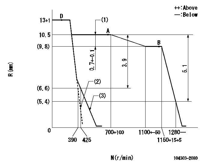
N:Pump speed
R:Rack position (mm)
(1)Rack difference between N = N1 and N = N2
(2)Set the idle spring.
(3)Main spring setting
----------
N1=700r/min N2=1150r/min
----------
----------
N1=700r/min N2=1150r/min
----------
Speed control lever angle
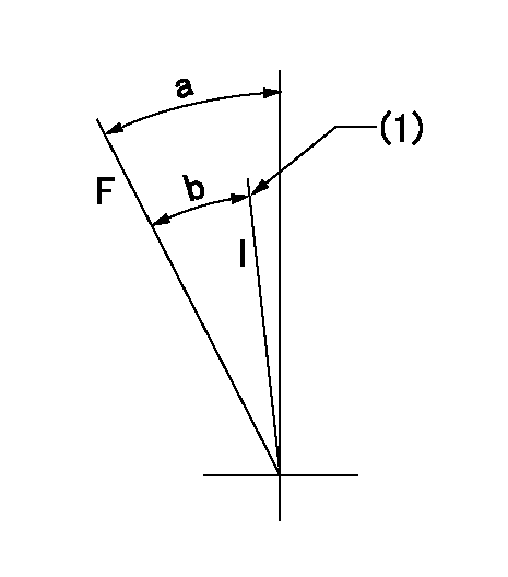
F:Full speed
I:Idle
(1)Stopper bolt setting
----------
----------
a=36deg+-3deg b=26deg+-6deg
----------
----------
a=36deg+-3deg b=26deg+-6deg
Stop lever angle

N:Pump normal
S:Stop the pump.
----------
----------
a=18deg+-5deg b=(38deg)
----------
----------
a=18deg+-5deg b=(38deg)
Timing setting

(1)Pump vertical direction
(2)Position of gear mark '00' at No 1 cylinder's beginning of injection
(3)B.T.D.C.: aa
(4)-
----------
aa=16deg
----------
a=(110deg)
----------
aa=16deg
----------
a=(110deg)
Information:
This screen will be displayed when the coolant temperature is below 0 degrees Celsius (0°C). This screen will be displayed when the coolant temperature is above 64 degrees Celsius (64°C).Fault Displays
This screen will be displayed if an internal fault is found.Refer to Service in this manual to return the DDT. This screen will be displayed if an internal fault is found.Refer to Troubleshooting the DDT in this manual. This screen will be displayed if the DDT is unable to talk (communicate) to the Electronic Control Module.Refer to Troubleshooting the DDT in this manual. This screen will be displayed if the Customer Passwords are requested and the passwords entered are found to be invalid. This screen will be displayed if the an engine rating function is selected and the engine is running. This screen will be displayed if the keypad is found to be faulty.Refer to Service in this manual to return the DDT. This screen will be displayed if a number is entered into the DDT for direct access to a nonexisting Mode or Function.Fault Code Translation Chart
Challenger 3176 EUI Fault Code Translation Chart
Mode/Function Chart
Troubleshooting the DDT
LCD display is blank:* Disconnect and reconnect T-harness cable or* Replace T-harness cable or* Service is required LCD display top line is black and bottom line is blank:* Disconnect and reconnect T-harness cable or* Remove and install the Service Program Module or* Service is required LCD display bottom line shows ' FAULT #E0':* Service is required LCD display bottom line shows ' FAULT #E1':* Remove and install the Service Program Module or* Service is required LCD display bottom line shows ' FAULT #E2':* Press CLEAR key to clear fault condition or* Disconnect and reconnect T-harness cable or* Check for power ON at the Electronic Control Module LCD display bottom line shows ' FAULT #E3':* Press CLEAR key to clear fault condition* Press ALT1 key* Reenter customer passwords LCD display bottom line shows ' FAULT #E4':* Turn engine OFF but leave power ON at the electronic control module* Press CLEAR key to clear fault condition LCD display bottom line shows ' SERVICE, KEYPAD':* Service is required LCD display bottom line shows ' Not received':* Abnormal, no fault message have been received LCD display bottom line shows ' NO FAULTS':* Normal, no faults have been received LCD display bottom line shows ' CONNECT 3176 ECM':* Connect the DDT to the correct Electronic Control Module LCD display bottom line shows ' UPDATE ECM':* Warning, the electronic control module that is connected to the DDT is not current. LCD display bottom line shows ' UPDATE DDT':* Warning, the DDTs service program module is not current LCD display bottom line shows ' NO SIGNAL' when a modulated signal is expected:* Disconnect and reconnect probe LCD display bottom line shows ' FREQ TOO LO':* Disconnect and reconnect probe LCD display bottom line shows ' FREQ TOO HI':* Disconnect and reconnect probe LCD display bottom line