Information injection-pump assembly
ZEXEL
104303-2060
1043032060
ISUZU
5156011601
5156011601

Rating:
Service parts 104303-2060 INJECTION-PUMP ASSEMBLY:
1.
_
3.
GOVERNOR
4.
SUPPLY PUMP
5.
AUTOM. ADVANCE MECHANIS
6.
COUPLING PLATE
7.
COUPLING PLATE
8.
_
9.
_
11.
Nozzle and Holder
5-15300-110-2
12.
Open Pre:MPa(Kqf/cm2)
11.8{120}

15.
NOZZLE SET
Include in #1:
104303-2060
as INJECTION-PUMP ASSEMBLY
Cross reference number
ZEXEL
104303-2060
1043032060
ISUZU
5156011601
5156011601
Zexel num
Bosch num
Firm num
Name
104303-2060
5156011601 ISUZU
INJECTION-PUMP ASSEMBLY
3AF1 * K 14BV PES3K PE
3AF1 * K 14BV PES3K PE
Calibration Data:
Adjustment conditions
Test oil
1404 Test oil ISO4113 or {SAEJ967d}
1404 Test oil ISO4113 or {SAEJ967d}
Test oil temperature
degC
40
40
45
Nozzle and nozzle holder
105780-8140
Bosch type code
EF8511/9A
Nozzle
105780-0000
Bosch type code
DN12SD12T
Nozzle holder
105780-2080
Bosch type code
EF8511/9
Opening pressure
MPa
17.2
Opening pressure
kgf/cm2
175
Injection pipe
Outer diameter - inner diameter - length (mm) mm 6-2-600
Outer diameter - inner diameter - length (mm) mm 6-2-600
Tester oil delivery pressure
kPa
157
157
157
Tester oil delivery pressure
kgf/cm2
1.6
1.6
1.6
Direction of rotation (viewed from drive side)
Right R
Right R
Injection timing adjustment
Direction of rotation (viewed from drive side)
Right R
Right R
Injection order
1-3-2
Pre-stroke
mm
2.1
2.05
2.15
Beginning of injection position
Drive side NO.1
Drive side NO.1
Difference between angles 1
Cal 1-3 deg. 120 119.5 120.5
Cal 1-3 deg. 120 119.5 120.5
Difference between angles 2
Cyl.1-2 deg. 240 239.5 240.5
Cyl.1-2 deg. 240 239.5 240.5
Injection quantity adjustment
Adjusting point
A
Rack position
9.7
Pump speed
r/min
700
700
700
Average injection quantity
mm3/st.
24.6
23.6
25.6
Max. variation between cylinders
%
0
-2.5
2.5
Basic
*
Fixing the lever
*
Injection quantity adjustment_02
Adjusting point
C
Rack position
7.1+-0.5
Pump speed
r/min
425
425
425
Average injection quantity
mm3/st.
6.5
5.5
7.5
Max. variation between cylinders
%
0
-14
14
Fixing the lever
*
Injection quantity adjustment_03
Adjusting point
D
Rack position
13+1
Pump speed
r/min
100
100
100
Average injection quantity
mm3/st.
37
37
Fixing the lever
*
Injection quantity adjustment_04
Adjusting point
-
Rack position
8.8
Pump speed
r/min
1150
1150
1150
Average injection quantity
mm3/st.
24
24
24
Fixing the lever
*
Test data Ex:
Governor adjustment
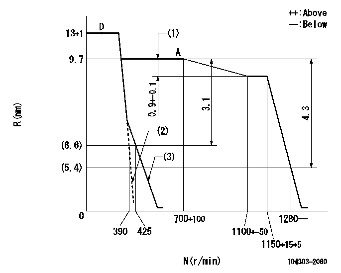
N:Pump speed
R:Rack position (mm)
(1)Rack difference between N = N1 and N = N2
(2)Set the idle spring.
(3)Main spring setting
----------
N1=700r/min N2=1150r/min
----------
----------
N1=700r/min N2=1150r/min
----------
Speed control lever angle
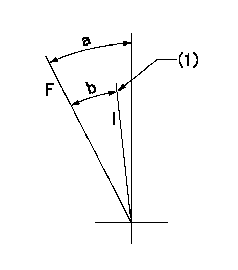
F:Full speed
I:Idle
(1)Stopper bolt setting
----------
----------
a=36deg+-3deg b=26deg+-6deg
----------
----------
a=36deg+-3deg b=26deg+-6deg
Stop lever angle

N:Pump normal
S:Stop the pump.
----------
----------
a=18deg+-5deg b=(38deg)
----------
----------
a=18deg+-5deg b=(38deg)
Timing setting

(1)Pump vertical direction
(2)Position of gear mark '00' at No 1 cylinder's beginning of injection
(3)B.T.D.C.: aa
(4)-
----------
aa=16deg
----------
a=(110deg)
----------
aa=16deg
----------
a=(110deg)
Information:
Test Points (Voltages And Waveforms)
dc Voltages Conditions: 1. dc input voltage applied to POWER connector as shown.2. CALIBRATION CHECK/OPERATE switch in the OPERATE position.3. Neither transducer connected to indicator.4. TPI is reference for all voltages.Equipment Required: 6V3030 Digital Multimeterdc Input Voltages Waveforms Conditions: 1. dc power input voltage of 25 1 Volts.2. CALIBRATION CHECK/OPERATE switch in the CHECK position (can be held in CHECK position with tape).3. Neither transducer connected to indicator.4. TPI is reference for all waveforms.Equipment Required: dc oscilloscope (dual channel preferred). Waveform Time Relationships
VOLTAGES MAY VARY 10%, PULSE DURATIONS BY 20% EXCEPT 2.66 ms WHICH IS BASED ON A 12.000 kHz OSCILLATOR FREQ. (1C202). SIGNAL SOURCE IS INTERNAL CALIBRATOR. ALL TEST POINTS REFERENCED TO TP1.Waveform Time Relationships (enlarged scale)
VOLTAGES MAY VARY 10%, PULSE DURATIONS BY 20% EXCEPT 83.3 ?s AND 2.66 ms WHICH ARE EXACT BASED ON A 12.000 kHZ OSCILLATOR. (1C202) SIGNAL SOURCE IS INTERNAL CALIBRATOR. ALL TEST POINTS REFERENCED TO TP1.Disassembly Procedure
1 Remove six screws (1) from front panel (2), and remove panel (2) from case (3). Remove four screws (4) from the PC board, and also remove the locknuts from the two front panel switches (5) and (6). Carefully lift front panel (2) from PC (printed circuit) board (7).Calibration Procedure
To make sure the 6V3100 Timing Indicator Group (1) has good accuracy, check its calibration at a minimum of every six months. Also, the timing indicator will need calibration if: A. It does not show 2000 30 R/MIN at (A) and 32.0 .2 DEG at (B), when the CALIBRATION CHECK-OPERATE Switch (C) is in the CALIBRATION CHECK position. With no input signal at (D) or (E), the reading at R/MIN location (A) must show three zeros (000). If four zeros (0000) show, it is an indication of a possible need for calibration of the unit. This error only is not reason enough to do a complete calibration procedure. It is also not necessary to do a complete calibration procedure if the reading at the DEG location (B) has a decimal point as shown, (00.0) in addition to the three zeros.B. Reading is different than (000) at either location (A) or (B).All calibrations can be done with the use of a small screwdriver, a frequency counter and
Have questions with 104303-2060?
Group cross 104303-2060 ZEXEL
Isuzu
104303-2060
5156011601
INJECTION-PUMP ASSEMBLY
3AF1
3AF1