Information injection-pump assembly
ZEXEL
104302-6680
1043026680

Rating:
Cross reference number
ZEXEL
104302-6680
1043026680
Zexel num
Bosch num
Firm num
Name
104302-6680
INJECTION-PUMP ASSEMBLY
KDL20 *
KDL20 *
Calibration Data:
Adjustment conditions
Test oil
1404 Test oil ISO4113 or {SAEJ967d}
1404 Test oil ISO4113 or {SAEJ967d}
Test oil temperature
degC
40
40
45
Nozzle and nozzle holder
105780-8140
Bosch type code
EF8511/9A
Nozzle
105780-0000
Bosch type code
DN12SD12T
Nozzle holder
105780-2080
Bosch type code
EF8511/9
Opening pressure
MPa
17.2
Opening pressure
kgf/cm2
175
Injection pipe
Outer diameter - inner diameter - length (mm) mm 6-2-600
Outer diameter - inner diameter - length (mm) mm 6-2-600
Tester oil delivery pressure
kPa
157
157
157
Tester oil delivery pressure
kgf/cm2
1.6
1.6
1.6
Direction of rotation (viewed from drive side)
Right R
Right R
Injection timing adjustment
Direction of rotation (viewed from drive side)
Right R
Right R
Injection order
1-2
Pre-stroke
mm
1.95
1.9
2
Beginning of injection position
Drive side NO.1
Drive side NO.1
Difference between angles 1
Cyl.1-2 deg. 90 89.5 90.5
Cyl.1-2 deg. 90 89.5 90.5
Injection quantity adjustment
Adjusting point
A
Rack position
7.8
Pump speed
r/min
1100
1100
1100
Average injection quantity
mm3/st.
29.5
28.5
30.5
Max. variation between cylinders
%
0
-2.5
2.5
Basic
*
Fixing the lever
*
Injection quantity adjustment_02
Adjusting point
B
Rack position
6.9
Pump speed
r/min
1800
1800
1800
Average injection quantity
mm3/st.
26
25
27
Max. variation between cylinders
%
0
-4
4
Fixing the lever
*
Injection quantity adjustment_03
Adjusting point
C
Rack position
5.8+-0.5
Pump speed
r/min
600
600
600
Average injection quantity
mm3/st.
10.5
9.5
11.5
Max. variation between cylinders
%
0
-14
14
Fixing the lever
*
Injection quantity adjustment_04
Adjusting point
D
Rack position
13+1
Pump speed
r/min
100
100
100
Average injection quantity
mm3/st.
45
45
Fixing the lever
*
Test data Ex:
Governor adjustment
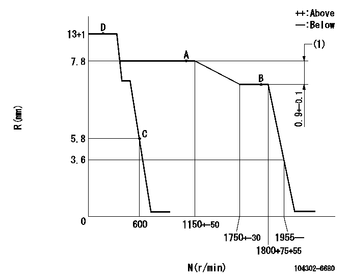
N:Pump speed
R:Rack position (mm)
(1)Rack difference between N = N1 and N = N2
----------
N1=1800r/min N2=1100r/min
----------
----------
N1=1800r/min N2=1100r/min
----------
Speed control lever angle
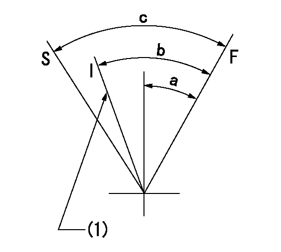
F:Full speed
I:Idle
S:Stop
(1)Set using the idle set spring.
----------
----------
a=24deg+-3deg b=34deg+-6deg c=47deg+-6deg
----------
----------
a=24deg+-3deg b=34deg+-6deg c=47deg+-6deg
Information:
Heavy Duty Air Cleaners
Generator set engines equipped with heavy duty air cleaners have a serviceable air cleaner element. The element may be cleaned up to six times, but must be replaced Every Year.Remove and Install Air Cleaner Elements
Heavy duty air cleaner:(1) service indicator(2) upper body (air filter element housing)(3) clamps(4) lower body (tube element)(5) dust collector cup1. Loosen clamps (3) between the lower body (4) and the dust collector cup (5). Remove the cup.2. Loosen the clamps between the lower body and the upper body (2). Remove the tube element.3. Clean the tubes from both sides with water or air.4. Remove the air filter element from the upper body (2). Wipe the inside of the upper body clean.5. Inspect and clean air filter element. Install a clean or new element.6. Inspect the gasket between the upper body and lower body. Inspect the seal between the lower body and the dust collector cup. Install a new gasket and seal if necessary.7. Install the cleaned, dry tube element. Tighten the retaining clamps attaching the lower body to the upper body.8. Wipe the dust collector cup clean. Install the cup and tighten the retaining clamps.9. Reset the service indicator (1).Cleaning Air Filter Elements
The primary element (Caterpillar air filters) can be cleaned several times before replacement. The element, when cleaned, should be thoroughly checked for rips or tears in the filter material.Replace the primary element at least EVERY YEAR regardless of operating hours it has accumulated.
Do not clean filter elements by bumping or tapping.Do not use filter elements with damaged pleats, gaskets or seals. Engine damage could result.
Filter elements can be cleaned with air pressure, 205 kPa (30 psi) maximum, or water pressure, 280 kPa (40 psi) maximum, or detergent washing. Have spare elements on hand to use while cleaning used elements.* Direct air or water along the length of the plate inside and outside of air filter element.The element can be washed in warm water and nonsudsing household detergent, such as automatic dishwasher detergent. Rinse inside and outside the pleats. The filter should then be thoroughly air dried and inspected.* Inspect the filter elements after cleaning for any rips, tears or damage. Insert a light inside of the clean, dry element. Do not use a filter element with damaged pleats, gaskets or seals. Discard the element if damaged.* Wrap and store the clean filter elements in a clean, dry place.* Reset the service indicator by pushing the piston plunger in.For more information on air cleaner element cleaning, refer to Guideline for Reusable Parts-Cleaning and Inspection of Air Filters, SEBU8062.Air Starter & Air Tank (If Equipped)
Check Lubricator Level
Never allow the lubricator bowl (if equipped) to become empty. The starting motor will be damaged by lack of proper lubrication.
The vanes of the starting motor are lubricated with a fine mist of oil from the motor lubricator. Check the level of oil in the lubricator bowl. If the bowl is less than half full, add lubricant. Use non detergent 10W engine oil for temperatures
Have questions with 104302-6680?
Group cross 104302-6680 ZEXEL
Toyo-Sha
Ishikawajima-S
Toyo-Sha
104302-6680
INJECTION-PUMP ASSEMBLY
KDL20
KDL20