Information injection-pump assembly
ZEXEL
104302-6610
1043026610
TOYO-SHA
5301510102
5301510102

Rating:
Service parts 104302-6610 INJECTION-PUMP ASSEMBLY:
1.
_
2.
FUEL INJECTION PUMP
3.
GOVERNOR
4.
SUPPLY PUMP
5.
AUTOM. ADVANCE MECHANIS
6.
COUPLING PLATE
7.
COUPLING PLATE
8.
_
9.
_
11.
Nozzle and Holder
12.
Open Pre:MPa(Kqf/cm2)
11.8{120}

15.
NOZZLE SET
Include in #1:
104302-6610
as INJECTION-PUMP ASSEMBLY
Cross reference number
ZEXEL
104302-6610
1043026610
TOYO-SHA
5301510102
5301510102
Zexel num
Bosch num
Firm num
Name
104302-6610
5301510102 TOYO-SHA
INJECTION-PUMP ASSEMBLY
2S100 *
2S100 *
Calibration Data:
Adjustment conditions
Test oil
1404 Test oil ISO4113 or {SAEJ967d}
1404 Test oil ISO4113 or {SAEJ967d}
Test oil temperature
degC
40
40
45
Nozzle and nozzle holder
105780-8140
Bosch type code
EF8511/9A
Nozzle
105780-0000
Bosch type code
DN12SD12T
Nozzle holder
105780-2080
Bosch type code
EF8511/9
Opening pressure
MPa
17.2
Opening pressure
kgf/cm2
175
Injection pipe
Outer diameter - inner diameter - length (mm) mm 6-2-600
Outer diameter - inner diameter - length (mm) mm 6-2-600
Tester oil delivery pressure
kPa
157
157
157
Tester oil delivery pressure
kgf/cm2
1.6
1.6
1.6
Direction of rotation (viewed from drive side)
Right R
Right R
Injection timing adjustment
Direction of rotation (viewed from drive side)
Right R
Right R
Injection order
1-2
Pre-stroke
mm
2.4
2.35
2.45
Rack position
After adjusting injection quantity. R=A
After adjusting injection quantity. R=A
Beginning of injection position
Drive side NO.1
Drive side NO.1
Difference between angles 1
Cyl.1-2 deg. 270 269.5 270.5
Cyl.1-2 deg. 270 269.5 270.5
Injection quantity adjustment
Adjusting point
A
Rack position
8.9
Pump speed
r/min
1150
1150
1150
Average injection quantity
mm3/st.
31.7
30.7
32.7
Max. variation between cylinders
%
0
-3
3
Basic
*
Fixing the lever
*
Injection quantity adjustment_02
Adjusting point
B
Rack position
9.4+-0.5
Pump speed
r/min
850
850
850
Average injection quantity
mm3/st.
33.7
32.7
34.7
Max. variation between cylinders
%
0
-4
4
Fixing the lever
*
Test data Ex:
Governor adjustment
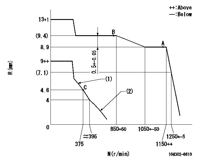
N:Pump speed
R:Rack position (mm)
(1)Set the idle spring.
(2)Set the governor spring.
----------
----------
----------
----------
Speed control lever angle

F:Full speed
I:Idle
(1)Stopper bolt setting
----------
----------
a=19deg+-6deg b=16deg+-3deg
----------
----------
a=19deg+-6deg b=16deg+-3deg
Stop lever angle
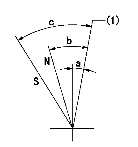
N:Pump normal
S:Stop the pump.
(1)At lever installation
----------
----------
a=5deg+-3deg b=18deg+-3deg c=(38deg)
----------
----------
a=5deg+-3deg b=18deg+-3deg c=(38deg)
Timing setting

(1)Pump vertical direction
(2)Position of camshaft's key groove at No 1 cylinder's beginning of injection
(3)B.T.D.C.: aa (at starting)
(4)-
----------
aa=13.5deg
----------
a=(40deg)
----------
aa=13.5deg
----------
a=(40deg)
Information:
Air Shutoff Solenoid (If Equipped)
This optional solenoid is located on top of the engine in the air inlet system. When the solenoid is activated, the solenoid mechanically shuts off inlet air to the engine. The solenoid can only be activated by the overspeed switch or the emergency stop switch.Fuel Shutoff Solenoid
This solenoid is located on the governor or on the fuel injection pump. When the solenoid is activated, the solenoid moves the fuel rack (either directly or through the governor) to the Fuel Off position.Overspeed Shutoffs
Magnetic pickup (1), mounted in the flywheel housing (2).A magnetic pickup mounted in the flywheel housing senses the passage of the flywheel ring gear teeth. Should the engine speed increase above the overspeed setting of the Electronic Speed Switch (118 percent of rated engine speed), the magnetic pickup will sense the overspeed. The overspeed condition activates both the air (if equipped) and fuel shutoff solenoids.The shutoffs must be reset before the engine will restart. A reset button on the Electronic Speed Switch (in the junction box) must be pushed to open the overspeed switch. The air shutoff lever (at the top of the air inlet housing) must be manually reset.If equipped with a Caterpillar Generator Set Control Panel, the devices on the panel must be reset after an overspeed shutoff. Turn the Engine Control Switch to the OFF/RESET position.Oil Pressure Switches
Typical example of oil pressure switches, mounted in the rear of the junction box.An oil pressure switch has wires connected to the electrical system for alarm or shutoff functions. The oil pressure switch senses oil pressure at the bearing oil gallery. If sufficient oil pressure is not achieved after engine starting, or if the engine has been running normally and then loses oil pressure, the fuel shutoff solenoid is energized to shut the engine off. No resetting procedure is required.Engine Step Oil Pressure
This is an adjustable engine speed setting that protects the engine from a failure caused by too little oil pressure for a specified speed range. This option requires two different oil pressure switches. One switch has a high pressure rating- when the engine is running above the speed setting, the engine must maintain oil pressure higher than the switch rating. The other switch has a low pressure rating- an engine running below the speed setting must maintain oil pressure above the low switch rating.In an automatic start/stop system, an automatic reset switch is used. Manually operated systems require the switch to be reset before the engine will start.
If the RESET button does not move to the extended position after the engine starts, the engine will NOT be protected by this particular switch.If the RESET button remains in the reset position, the engine oil pump will not develop normal oil pressure. An inspection should be made to correct the problem.
In order to reset the switch, push the RESET button until the button latches. After the engine starts and develops oil pressure, the button will move to the extended (running) position.
The button must
Have questions with 104302-6610?
Group cross 104302-6610 ZEXEL
Toyo-Sha
104302-6610
5301510102
INJECTION-PUMP ASSEMBLY
2S100
2S100