Information injection-pump assembly
BOSCH
9 400 616 421
9400616421
ZEXEL
104302-6600
1043026600
TOYO-SHA
5601510102
5601510102

Rating:
Service parts 104302-6600 INJECTION-PUMP ASSEMBLY:
1.
_
3.
GOVERNOR
4.
SUPPLY PUMP
5.
AUTOM. ADVANCE MECHANIS
6.
COUPLING PLATE
7.
COUPLING PLATE
8.
_
9.
_
11.
Nozzle and Holder
12.
Open Pre:MPa(Kqf/cm2)
11.8{120}

15.
NOZZLE SET
Include in #1:
104302-6600
as INJECTION-PUMP ASSEMBLY
Cross reference number
BOSCH
9 400 616 421
9400616421
ZEXEL
104302-6600
1043026600
TOYO-SHA
5601510102
5601510102
Zexel num
Bosch num
Firm num
Name
104302-6600
9 400 616 421
5601510102 TOYO-SHA
INJECTION-PUMP ASSEMBLY
2S107 K 14BT INJECTION PUMP ASSY PES2K PE
2S107 K 14BT INJECTION PUMP ASSY PES2K PE
Calibration Data:
Adjustment conditions
Test oil
1404 Test oil ISO4113 or {SAEJ967d}
1404 Test oil ISO4113 or {SAEJ967d}
Test oil temperature
degC
40
40
45
Nozzle and nozzle holder
105780-8140
Bosch type code
EF8511/9A
Nozzle
105780-0000
Bosch type code
DN12SD12T
Nozzle holder
105780-2080
Bosch type code
EF8511/9
Opening pressure
MPa
17.2
Opening pressure
kgf/cm2
175
Injection pipe
Outer diameter - inner diameter - length (mm) mm 6-2-600
Outer diameter - inner diameter - length (mm) mm 6-2-600
Tester oil delivery pressure
kPa
157
157
157
Tester oil delivery pressure
kgf/cm2
1.6
1.6
1.6
Direction of rotation (viewed from drive side)
Right R
Right R
Injection timing adjustment
Direction of rotation (viewed from drive side)
Right R
Right R
Injection order
1-2
Pre-stroke
mm
2.4
2.35
2.45
Rack position
After adjusting injection quantity. R=A
After adjusting injection quantity. R=A
Beginning of injection position
Drive side NO.1
Drive side NO.1
Difference between angles 1
Cyl.1-2 deg. 270 269.5 270.5
Cyl.1-2 deg. 270 269.5 270.5
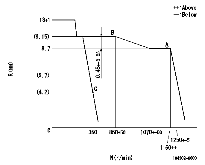
Injection quantity adjustment
Adjusting point
A
Rack position
8.7
Pump speed
r/min
1150
1150
1150
Average injection quantity
mm3/st.
35.5
34.5
36.5
Max. variation between cylinders
%
0
-3
3
Basic
*
Fixing the lever
*
Injection quantity adjustment_02
Adjusting point
B
Rack position
9.15
Pump speed
r/min
850
850
850
Average injection quantity
mm3/st.
37
36
38
Max. variation between cylinders
%
0
-4
4
Fixing the lever
*
Injection quantity adjustment_03
Adjusting point
C
Rack position
4.2+-0.5
Pump speed
r/min
350
350
350
Average injection quantity
mm3/st.
12.6
11.6
13.6
Max. variation between cylinders
%
0
-14
14
Fixing the lever
*
Test data Ex:
Governor adjustment
N:Pump speed
R:Rack position (mm)
----------
----------
----------
----------
Speed control lever angle

F:Full speed
I:Idle
(1)Stopper bolt setting
----------
----------
a=19deg+-6deg b=16deg+-3deg
----------
----------
a=19deg+-6deg b=16deg+-3deg
Stop lever angle

N:Pump normal
S:Stop the pump.
----------
----------
a=18deg+-3deg b=(38deg)
----------
----------
a=18deg+-3deg b=(38deg)
Timing setting

(1)Pump vertical direction
(2)Position of camshaft's key groove at No 1 cylinder's beginning of injection
(3)B.T.D.C.: aa (at starting)
(4)-
----------
aa=12.5deg
----------
a=(40deg)
----------
aa=12.5deg
----------
a=(40deg)
Information:
Display
The upper display (1) and lower display (2) of the GSC provide information about the generator set.* The upper display (1) shows AC voltage, current, and frequency of one phase of the generator output. Each phase can be viewed one at a time by pushing phase select key (4). The upper display (1) is also used to show the various fault codes for system faults. For more information on fault codes, refer to the Service Manual Module SENR5809 for Fault Descriptions.* The lower display (2) shows: system battery voltage, engine hours, engine speed, engine oil pressure, and engine coolant temperature. The value for one of those conditions is displayed for two seconds, then the display scrolls to the value for the next condition. A small pointer identifies the engine condition that corresponds to the value that is showing. When engine meter key (3) is pressed, the lower display stops scrolling and continuously shows one particular value. The pointer flashes above the condition whose value is showing. When the engine meter key is pressed a second time, the display returns to scrolling.* The lower display also shows a relay status indicator. When a GSC relay is activated, the corresponding relay indicator (K1, K2, etc.) is shown on lower display (2). When a relay is not activated, the corresponding indicator (K1, K2, etc.) is not shown. Refer to the Service Manual Module SENR5809 for a description of the relay functions.Both the upper and lower display are used for programming functions when in the service mode. For more information, refer to the Service Manual Module SENR5809 for Service Modes.Keypad
The keypad (3) is used to control the information that is shown on upper display (1) and the lower display (2). The seven keys of keypad have two sets of functions: normal functions and service functions. For a description of the service functions of the keys, refer to the Service Manual Module SENR5809 for Service Models. The normal functions of the keys are as follows. Leftmost key (5) - This key only functions when the GSC is in the service mode. This key is used to scroll right. PHASE SELECT key (6) - This key selects which phase of the generator output shows on the GSC upper display. Pressing this key allows the operator to check the voltage, current, and frequency of each phase, one at a time. ENGINE METER key (7) - This key stops the scrolling of engine conditions on the lower display (2). The lower display continuously shows the value for one particular engine condition. The pointer for the particular engine condition flashes to indicate scrolling is stopped. Pressing the key again resumes the scrolling. LAMP TEST key (8) - This key perfumes a lamp test on the GSC and the optional alarm module for a maximum of ten seconds, if held pressed. On the GSC: the eight fault indicators are ON CONTINUOUSLY - every segment of the upper display (1) and the lower display (2) are ON. For the
Have questions with 104302-6600?
Group cross 104302-6600 ZEXEL
Toyo-Sha
104302-6600
9 400 616 421
5601510102
INJECTION-PUMP ASSEMBLY
2S107
2S107