Information injection-pump assembly
BOSCH
9 400 610 302
9400610302
ZEXEL
104302-6480
1043026480
TOYO-SHA
2281510101
2281510101
Rating:
Service parts 104302-6480 INJECTION-PUMP ASSEMBLY:
1.
_
3.
GOVERNOR
4.
SUPPLY PUMP
5.
AUTOM. ADVANCE MECHANIS
6.
COUPLING PLATE
7.
COUPLING PLATE
8.
_
9.
_
11.
Nozzle and Holder
2251-1210-01
12.
Open Pre:MPa(Kqf/cm2)
12.7{130}

15.
NOZZLE SET
Include in #1:
104302-6480
as INJECTION-PUMP ASSEMBLY
Cross reference number
BOSCH
9 400 610 302
9400610302
ZEXEL
104302-6480
1043026480
TOYO-SHA
2281510101
2281510101
Zexel num
Bosch num
Firm num
Name
104302-6480
9 400 610 302
2281510101 TOYO-SHA
INJECTION-PUMP ASSEMBLY
S126 K 14BT INJECTION PUMP ASSY PES2K PE
S126 K 14BT INJECTION PUMP ASSY PES2K PE
Calibration Data:
Adjustment conditions
Test oil
1404 Test oil ISO4113 or {SAEJ967d}
1404 Test oil ISO4113 or {SAEJ967d}
Test oil temperature
degC
40
40
45
Nozzle and nozzle holder
105780-8140
Bosch type code
EF8511/9A
Nozzle
105780-0000
Bosch type code
DN12SD12T
Nozzle holder
105780-2080
Bosch type code
EF8511/9
Opening pressure
MPa
17.2
Opening pressure
kgf/cm2
175
Injection pipe
Outer diameter - inner diameter - length (mm) mm 6-2-600
Outer diameter - inner diameter - length (mm) mm 6-2-600
Tester oil delivery pressure
kPa
157
157
157
Tester oil delivery pressure
kgf/cm2
1.6
1.6
1.6
Direction of rotation (viewed from drive side)
Right R
Right R
Injection timing adjustment
Direction of rotation (viewed from drive side)
Right R
Right R
Injection order
1-2
Pre-stroke
mm
1.95
1.9
2
Rack position
Point A R=A
Point A R=A
Beginning of injection position
Drive side NO.1
Drive side NO.1
Difference between angles 1
Cyl.1-2 deg. 270 269.5 270.5
Cyl.1-2 deg. 270 269.5 270.5
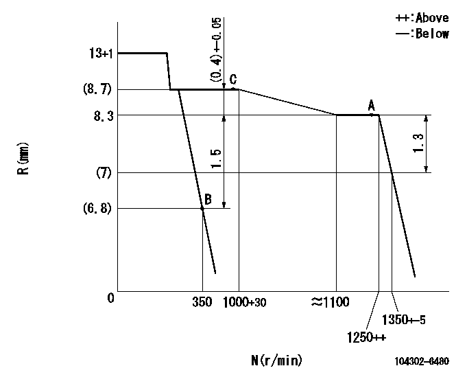
Injection quantity adjustment
Adjusting point
A
Rack position
8.3
Pump speed
r/min
1250
1250
1250
Average injection quantity
mm3/st.
43
42
44
Max. variation between cylinders
%
0
-3
3
Basic
*
Fixing the lever
*
Injection quantity adjustment_02
Adjusting point
B
Rack position
6.8+-0.5
Pump speed
r/min
350
350
350
Average injection quantity
mm3/st.
6
5
7
Max. variation between cylinders
%
0
-14
14
Fixing the lever
*
Test data Ex:
Governor adjustment
N:Pump speed
R:Rack position (mm)
----------
----------
----------
----------
Speed control lever angle
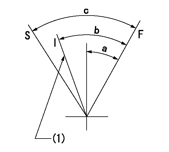
F:Full speed
I:Idle
S:Stop
(1)Set idling using the idle set spring.
----------
----------
a=16deg+-3deg b=22deg+-6deg c=(33deg)
----------
----------
a=16deg+-3deg b=22deg+-6deg c=(33deg)
Stop lever angle

N:Pump normal
S:Stop the pump.
----------
----------
a=18deg+-3deg b=(38deg)
----------
----------
a=18deg+-3deg b=(38deg)
Information:
Literature Information
This manual contains information and instructions concerning engine safety, operation, lubrication, and maintenance. Read, study, and keep it available with other literature and engine information.Some photographs or illustrations in this publication show details or attachments that may differ from your engine. Guards and covers may have been removed for illustrative purposes. Continuing improvement and advancement of product design may have caused changes to your engine which are not included in this publication.Whenever a question arises regarding your engine, or this publication, please consult your Caterpillar dealer for the latest available information.Safety
The safety section lists basic safety precautions. In addition, this section identifies hazardous, warning situations. Read and understand the basic precautions listed in the safety section before operating or performing lubrication, maintenance and/or repair on this product.Operation
Engine operation outlined in this publication is basic. Engine operators gain knowledge of the engine through experience, developing operation skills and techniques which enhance efficient and economical engine operation.The operation section is a reference for operators. Photographs and illustrations guide operators through correct procedures of inspecting, starting, operating and stopping the engine. Discussion of gauges and engine control information is included.Maintenance
The maintenance section is a guide to engine care. The illustrated instructions are grouped by maintenance service intervals. The actual operating environment of the engine also governs the maintenance schedule. Under extremely severe, dusty, or frigid operating conditions, lubrication and maintenance checks more frequent than those specified in the Maintenance Schedule may be necessary. Maintenance Intervals
Use the service hour meter to determine service intervals. Calendar intervals shown (daily, weekly, monthly, etc.) can be used instead of service hour meter intervals, if they provide more convenient serving schedules and approximate the indicated service hour meter reading. Recommended service should always be performed at the interval that occurs first.We recommend that the maintenance schedules be reproduced for ease of inspection. We also recommend that ongoing maintenance records be kept to document engine service. See the Maintenance Records section of this publication for information regarding documents that are generally accepted as proof of maintenance or repair. Your Caterpillar dealer can assist you in tailoring your Maintenance Schedule to meet the needs of your operating environment.Overhaul
Major engine repair details are not covered in this manual. Major repairs are best left to trained personnel or an authorized Caterpillar dealer.If a major engine failure requiring removal of the engine occurs, numerous after-failure overhaul options available from your Caterpillar dealer. Contact your dealer for information regarding these options.Engine Description
The engines described in this publication are the 3408C and 3412C Industrial and EPG diesel engines.They are designed primarily for agricultural, prime power and standby electrical power generation, petroleum and auxiliary industrial applications.Engine Storage
For general information, refer to the Engine Lifting & Storage topic. For complete engine storage information refer to Special Instruction SEHS9031, Storage Procedure for Caterpillar Products.California Proposition 65 Warning
Diesel engine exhaust and some of its constituents are known to the State of California to cause cancer, birth defects, and other reproductive harm.
Have questions with 104302-6480?
Group cross 104302-6480 ZEXEL
Ishikawajima-S
Isuzu
Toyo-Sha
104302-6480
9 400 610 302
2281510101
INJECTION-PUMP ASSEMBLY
S126
S126