Information injection-pump assembly
BOSCH
9 400 616 416
9400616416
ZEXEL
104302-6440
1043026440
TOYO-SHA
2801250103
2801250103
Rating:
Service parts 104302-6440 INJECTION-PUMP ASSEMBLY:
1.
_
3.
GOVERNOR
4.
SUPPLY PUMP
5.
AUTOM. ADVANCE MECHANIS
6.
COUPLING PLATE
7.
COUPLING PLATE
8.
_
9.
_
11.
Nozzle and Holder
2251-1210-01
12.
Open Pre:MPa(Kqf/cm2)
12.7{130}

15.
NOZZLE SET
Include in #1:
104302-6440
as INJECTION-PUMP ASSEMBLY
Cross reference number
BOSCH
9 400 616 416
9400616416
ZEXEL
104302-6440
1043026440
TOYO-SHA
2801250103
2801250103
Zexel num
Bosch num
Firm num
Name
104302-6440
9 400 616 416
2801250103 TOYO-SHA
INJECTION-PUMP ASSEMBLY
S148 * K 14BT INJECTION PUMP ASSY PES2K PE
S148 * K 14BT INJECTION PUMP ASSY PES2K PE
Calibration Data:
Adjustment conditions
Test oil
1404 Test oil ISO4113 or {SAEJ967d}
1404 Test oil ISO4113 or {SAEJ967d}
Test oil temperature
degC
40
40
45
Nozzle and nozzle holder
105780-8140
Bosch type code
EF8511/9A
Nozzle
105780-0000
Bosch type code
DN12SD12T
Nozzle holder
105780-2080
Bosch type code
EF8511/9
Opening pressure
MPa
17.2
Opening pressure
kgf/cm2
175
Injection pipe
Outer diameter - inner diameter - length (mm) mm 6-2-600
Outer diameter - inner diameter - length (mm) mm 6-2-600
Tester oil delivery pressure
kPa
157
157
157
Tester oil delivery pressure
kgf/cm2
1.6
1.6
1.6
Direction of rotation (viewed from drive side)
Right R
Right R
Injection timing adjustment
Direction of rotation (viewed from drive side)
Right R
Right R
Injection order
1-2
Pre-stroke
mm
1.95
1.9
2
Rack position
Point A R=A
Point A R=A
Beginning of injection position
Drive side NO.1
Drive side NO.1
Difference between angles 1
Cyl.1-2 deg. 270 269.5 270.5
Cyl.1-2 deg. 270 269.5 270.5
Injection quantity adjustment
Adjusting point
A
Rack position
9.3
Pump speed
r/min
1250
1250
1250
Average injection quantity
mm3/st.
50.5
49.5
51.5
Max. variation between cylinders
%
0
-3
3
Basic
*
Fixing the lever
*
Injection quantity adjustment_02
Adjusting point
B
Rack position
7.3+-0.5
Pump speed
r/min
350
350
350
Average injection quantity
mm3/st.
6
5
7
Max. variation between cylinders
%
0
-14
14
Fixing the lever
*
Test data Ex:
Governor adjustment
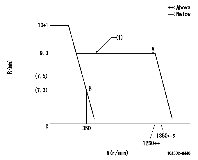
N:Pump speed
R:Rack position (mm)
(1)Deliver without the torque control spring operating.
----------
----------
----------
----------
Speed control lever angle
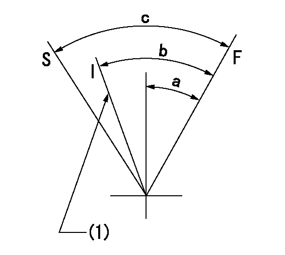
F:Full speed
I:Idle
S:Stop
(1)Set idling using the idle set spring.
----------
----------
a=16deg+-3deg b=22deg+-6deg c=(33deg)
----------
----------
a=16deg+-3deg b=22deg+-6deg c=(33deg)
Information:
Insert the special tool, Piston Ring Inserter to the turbine wheel and install the piston ring.(4) Installation of turbine wheel assembly Install using care not to damage the piston ring. After installation, turn the turbine wheel manually to check that it turns smoothly. If not, disassemble and reassemble again.(5) Installation of compressor wheel (a) Holding the center housing and turbine wheel shaft with fingers, insert slowly into the special tool, Holding Fixture. 1. When inserting, use care not to damage the turbine wheel assembly blades.2. Do not release the shaft before insertion as otherwise the turbine wheel assembly will drop. (b) After tightening the lock nut to specified torque, tighten additionally 110° using special tool, T-handle. Use care not to bend the shaft of turbine wheel assembly.(6) Installation of turbine housing Apply MOLYKOTE to the turbine housing attaching bolt threads and tighten temporarily. Then align match marks and tighten to specified torque. Use care not to damage the turbine wheel assembly blades.(7) Inspection of shaft play [Refer to Item (1) and (2), Section 5.3.1.](8) Installation of compressor housing (a) Lay the compressor housing on the back plate and face the compressor housing downward.(b) Align match marks put at time of disassembly and tighten to specified torque.(9) After assembly, turn the turbine wheel and compressor wheel manually to check that they turn smoothly. If they turn heavily or irregularly, disassemble and check causes.5.4 TD07 Turbocharger
Disassembly
Disassembly Procedure(1) Removal of turbine housing If the turbine housing is hard to remove, tap the turbine housing on its periphery using a plastic hammer or similar tool. The turbine wheel blades are easy to bend. Use care not to damage them.(2) Removal of compressor cover Using a plastic hammer or the similar tool, tap the compressor cover on its periphery and remove. Be careful not to hit the compressor wheel against compressor cover as its blades are easy to bend.(3) Removal of compressor wheel (a) Fit the bearing housing into the turbine housing which is clamped in a vise. (b) Hold the boss on the turbine wheel and remove the lock nut that attaches the compressor wheel. (c) Slowly lift up the compressor wheel to remove it.(4) Removal of insert (a) Remove the snap ring holding the insert into the bearing housing. Retain the snap ring by hand to prevent it from springing out when slipping off the snap ring pliers. (b) Hook the tips of the screwdrivers to the insert at the positions shown in the illustration, then carefully pry up the insert and thrust sleeve as a unit to remove them.Inspection and cleaning
Inspection Procedure(1) Cleaning (a) Immerse disassembled parts in a nonflammable solvent (Daido Kagaku Kogyo's Dai Cleaner T-30 or equivalent) to clean oily contamination. When a commercially-available neutral detergent is used for cleaning, make sure that it does not contain corrosive component. (b) Blow compressed air against the entire internal and external surfaces. (c) Using a plastic scraper or bristle brush, remove deposits from the surfaces. Then, dip parts in the
Have questions with 104302-6440?
Group cross 104302-6440 ZEXEL
Ishikawajima-S
Isuzu
Toyo-Sha
104302-6440
9 400 616 416
2801250103
INJECTION-PUMP ASSEMBLY
S148
S148