Information injection-pump assembly
BOSCH
9 400 610 086
9400610086
ZEXEL
104302-6420
1043026420
TOYO-SHA
22512501020
22512501020
Rating:
Service parts 104302-6420 INJECTION-PUMP ASSEMBLY:
1.
_
3.
GOVERNOR
4.
SUPPLY PUMP
5.
AUTOM. ADVANCE MECHANIS
6.
COUPLING PLATE
7.
COUPLING PLATE
8.
_
9.
_
11.
Nozzle and Holder
5701-1210-00
12.
Open Pre:MPa(Kqf/cm2)
12.7{130}

15.
NOZZLE SET
Include in #1:
104302-6420
as INJECTION-PUMP ASSEMBLY
Cross reference number
BOSCH
9 400 610 086
9400610086
ZEXEL
104302-6420
1043026420
TOYO-SHA
22512501020
22512501020
Zexel num
Bosch num
Firm num
Name
104302-6420
9 400 610 086
22512501020 TOYO-SHA
INJECTION-PUMP ASSEMBLY
S126 K 14BT INJECTION PUMP ASSY PES2K PE
S126 K 14BT INJECTION PUMP ASSY PES2K PE
Calibration Data:
Adjustment conditions
Test oil
1404 Test oil ISO4113 or {SAEJ967d}
1404 Test oil ISO4113 or {SAEJ967d}
Test oil temperature
degC
40
40
45
Nozzle and nozzle holder
105780-8140
Bosch type code
EF8511/9A
Nozzle
105780-0000
Bosch type code
DN12SD12T
Nozzle holder
105780-2080
Bosch type code
EF8511/9
Opening pressure
MPa
17.2
Opening pressure
kgf/cm2
175
Injection pipe
Outer diameter - inner diameter - length (mm) mm 6-2-600
Outer diameter - inner diameter - length (mm) mm 6-2-600
Tester oil delivery pressure
kPa
157
157
157
Tester oil delivery pressure
kgf/cm2
1.6
1.6
1.6
Direction of rotation (viewed from drive side)
Right R
Right R
Injection timing adjustment
Direction of rotation (viewed from drive side)
Right R
Right R
Injection order
1-2
Pre-stroke
mm
1.95
1.9
2
Rack position
Point A R=A
Point A R=A
Beginning of injection position
Drive side NO.1
Drive side NO.1
Difference between angles 1
Cyl.1-2 deg. 270 269.5 270.5
Cyl.1-2 deg. 270 269.5 270.5
Injection quantity adjustment
Adjusting point
A
Rack position
8
Pump speed
r/min
1250
1250
1250
Average injection quantity
mm3/st.
41
40
42
Max. variation between cylinders
%
0
-3
3
Basic
*
Fixing the lever
*
Injection quantity adjustment_02
Adjusting point
B
Rack position
6.3+-0.5
Pump speed
r/min
350
350
350
Average injection quantity
mm3/st.
6
5
7
Max. variation between cylinders
%
0
-14
14
Fixing the lever
*
Test data Ex:
Governor adjustment
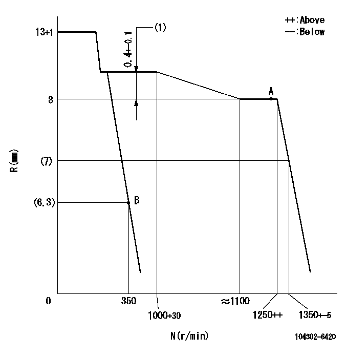
N:Pump speed
R:Rack position (mm)
(1)Rack difference between N = N1 and N = N2
----------
N1=1250r/min N2=1000r/min
----------
----------
N1=1250r/min N2=1000r/min
----------
Speed control lever angle
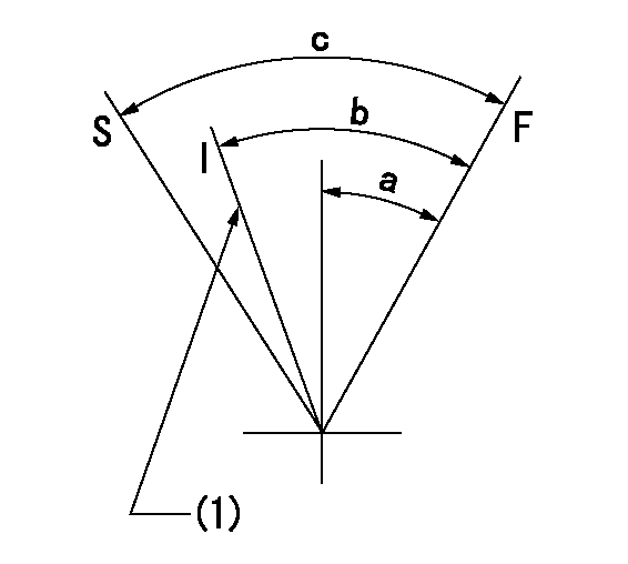
F:Full speed
I:Idle
S:Stop
(1)Set idling using the idle set spring.
----------
----------
a=16deg+-3deg b=22deg+-6deg c=33deg+-6deg
----------
----------
a=16deg+-3deg b=22deg+-6deg c=33deg+-6deg
Information:
(3) Check the unit seals installed in the impeller and water pump case for damage and wear. If defects are evident, or when water leaks during operation, replace the unit seals with new ones. Whenever the unit seal is removed, it must be replaced with a new one. (4) Using a gear puller or press, remove the ball bearings. Do not remove the ball bearing except for replacement. (5) When the impeller and flange are removed from the water pump shaft, it may result in insufficient interference. If the interference is below the specification even reassembly is two times or less they must be replaced with new ones.Reassembly
5.3 Thermostat
Removal and installation
Do not remove the thermostat case and front hanger unless they cause water leak or other defects.Inspection
Agitate water in the container with the stirrer to obtain uniform temperature. For the inspection, use the following procedures. (1) Slowly heat water to the thermostat valve opening temperature. Keep this condition for about five minutes and make sure that the valve is open.(2) Raise the water temperature up to 90°C. Keep the condition for five minutes and measure the lift of pellet.(3) Lower temperature down to 65°C or below and ensure that the valve is fully closed. If the thermostat is found defective in any of the above items, replace it with a new one. Support the thermostat so that the heat source will not directly heat the thermostat.5.4 Radiator
Inspection (1) Using a copper wire or similar device, remove dirt, mud, and bugs from the front of radiator core with care to prevent damage to tubings. (2) Connect a hose to one of the radiator ports, cap the other port, and immerse the radiator into water. Using a radiator cap tester, force the compressed air under the specified inspection pressure from the hose end to check for leaks.If there is a leak, resolder the point of leakage or replace the radiator.(3) Inspection of Radiator Cap Check the spring tension and sealing condition of the pressure valve and vent valve. If defective, replace. Check the pressure valve opening pressure, using a radiator cap tester.5.5 Inspection and Adjustment of V-belt Tension
Adjust the belt tension to obtain the specified belt deflection when the center of each belt is pressed with a force of approximately 98 N (10 kgf). 1. A slack belt can be a cause of overheating and undercharge.2. An excessively tight belt may result in damaged bearings and belts.3. When paired belts are to be replaced, be sure to replace both.5.6 Cleaning of Cooling System
If the radiator is used for a long time, rust, scale, mud, etc. are deposited inside, resulting in overheat. Clean the cooling system with city water by using the following procedures.The city water to be used should have the following properties.Required properties of city water 1. Use a cleaning solution if the radiator is seriously obstructed or coolant is seriously contaminated.2. When the cooling system is cleaned or washed with water, make sure that the coolant temperature is
Have questions with 104302-6420?
Group cross 104302-6420 ZEXEL
Ishikawajima-S
Isuzu
Toyo-Sha
104302-6420
9 400 610 086
22512501020
INJECTION-PUMP ASSEMBLY
S126
S126