Information injection-pump assembly
ZEXEL
104302-6050
1043026050
TOYO-SHA
3001250101
3001250101

Rating:
Service parts 104302-6050 INJECTION-PUMP ASSEMBLY:
1.
_
3.
GOVERNOR
4.
SUPPLY PUMP
5.
AUTOM. ADVANCE MECHANIS
6.
COUPLING PLATE
7.
COUPLING PLATE
8.
_
9.
_
11.
Nozzle and Holder
12.
Open Pre:MPa(Kqf/cm2)
12.7{130}

15.
NOZZLE SET
Include in #1:
104302-6050
as INJECTION-PUMP ASSEMBLY
Cross reference number
ZEXEL
104302-6050
1043026050
TOYO-SHA
3001250101
3001250101
Zexel num
Bosch num
Firm num
Name
Calibration Data:
Adjustment conditions
Test oil
1404 Test oil ISO4113 or {SAEJ967d}
1404 Test oil ISO4113 or {SAEJ967d}
Test oil temperature
degC
40
40
45
Nozzle and nozzle holder
105780-8140
Bosch type code
EF8511/9A
Nozzle
105780-0000
Bosch type code
DN12SD12T
Nozzle holder
105780-2080
Bosch type code
EF8511/9
Opening pressure
MPa
17.2
Opening pressure
kgf/cm2
175
Injection pipe
Outer diameter - inner diameter - length (mm) mm 6-2-600
Outer diameter - inner diameter - length (mm) mm 6-2-600
Overflow valve
132424-0620
Overflow valve opening pressure
kPa
157
123
191
Overflow valve opening pressure
kgf/cm2
1.6
1.25
1.95
Tester oil delivery pressure
kPa
157
157
157
Tester oil delivery pressure
kgf/cm2
1.6
1.6
1.6
Direction of rotation (viewed from drive side)
Right R
Right R
Injection timing adjustment
Direction of rotation (viewed from drive side)
Right R
Right R
Injection order
1-2
Pre-stroke
mm
1.95
1.9
2
Beginning of injection position
Drive side NO.1
Drive side NO.1
Difference between angles 1
Cyl.1-2 deg. 270 269.5 270.5
Cyl.1-2 deg. 270 269.5 270.5
Injection quantity adjustment
Adjusting point
A
Rack position
6.7
Pump speed
r/min
1150
1150
1150
Average injection quantity
mm3/st.
28.5
27.5
29.5
Max. variation between cylinders
%
0
-3
3
Basic
*
Fixing the lever
*
Injection quantity adjustment_02
Adjusting point
D
Rack position
5+-0.5
Pump speed
r/min
350
350
350
Average injection quantity
mm3/st.
6
5
7
Max. variation between cylinders
%
0
-14
14
Fixing the lever
*
Injection quantity adjustment_03
Adjusting point
F
Rack position
-
Pump speed
r/min
100
100
100
Average injection quantity
mm3/st.
42
35
49
Fixing the lever
*
Test data Ex:
Governor adjustment
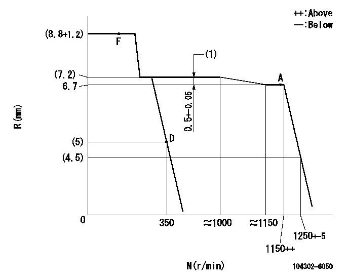
N:Pump speed
R:Rack position (mm)
(1)Torque control stroke
----------
----------
----------
----------
Speed control lever angle
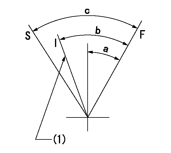
F:Full speed
I:Idle
S:Stop
(1)Set idling using the idle set spring.
----------
----------
a=27deg+-2deg b=28deg+-6deg c=(40deg)
----------
----------
a=27deg+-2deg b=28deg+-6deg c=(40deg)
Information:
Introduction
The objective of this topic is to assist users in establishing a Preventive Maintenance Program for Standby Generator Sets or as an aid in evaluating their present programs.Standby Generator Sets may not be needed very often, but when they are, it is usually under emergency conditions. Maintenance of these standby units is very important. They must always be in excellent operating condition, ready to work under load at any time.Establishing a Preventive Maintenance Program will provide maximum availability of a standby generator set when needed, longer engine and generator life, and a minimum of expensive repairs.The recommended WEEKLY maintenance checks can be performed by an operator. The checks consist of basic maintenance requirements to ensure the standby generator set will be ready for immediate use should the need arise.All YEARLY and THREE YEAR maintenance should be performed by an authorized mechanic or your Caterpillar dealer. These checks and maintenance requirements will require that the standby generator be run under load conditions, and may require special test equipment.These guidelines are to be used with the information contained in the Operation and Maintenance sections of this manual. The Operation and Maintenance sections of the manual will provide the necessary information on how to perform the checks and routine maintenance.Refer to the Generator and Engine Service Manuals and Recommended Preventive Maintenance Schedules for Standby Generator Sets, SEBU6042 for additional information, or contact your Caterpillar dealer for assistance.Inspection and Maintenance Agreements
Your Caterpillar dealer can establish an Inspection and Preventive Maintenance Program for your generator set to provide maximum reliability, increased engine and generator life, and minimize expensive repairs. Contact your Caterpillar dealer for details.General Recommendations
Safety
The stop-manual-automatic switch on the cranking panel must be set at STOP position when performing maintenance or repair work on a standby generator set. This prevents the unit from starting if a power failure or voltage drop should occur while working on the unit.To prevent personal injury due to accidental starting of the engine, disconnect the batteries or disable the starting system before doing maintenance or repair work.Lock out all switch gear and automatic transfer switches associated with the generator while performing any generator maintenance or repairs. Make sure no shock hazard exists.Failure to comply could result in personal injury or death.
Always make repairs with the engine stopped and the starting system disabled. When servicing the generator, make sure that switch gear and automatic transfer switches will not present a shock hazard. Lock them out on the generator being serviced.Record Keeping
Maintain a log or record keeping system to document all gauge readings, problems, repairs, and maintenance performed on the equipment.Space Heaters
Moisture is a natural enemy of generators and all electrical equipment. Every effort must be made to keep the generator as dry as possible. Space heaters should be operated inside the generator when it is not in use to maintain the integrity of the generator windings.