Information injection-pump assembly
ZEXEL
104302-6030
1043026030
Rating:
Service parts 104302-6030 INJECTION-PUMP ASSEMBLY:
1.
_
2.
FUEL INJECTION PUMP
3.
GOVERNOR
4.
SUPPLY PUMP
5.
AUTOM. ADVANCE MECHANIS
6.
COUPLING PLATE
7.
COUPLING PLATE
8.
_
9.
_
11.
Nozzle and Holder
2251-1210-01
12.
Open Pre:MPa(Kqf/cm2)
12.7{130}

15.
NOZZLE SET
Include in #1:
104302-6030
as INJECTION-PUMP ASSEMBLY
Cross reference number
ZEXEL
104302-6030
1043026030
Zexel num
Bosch num
Firm num
Name
Calibration Data:
Adjustment conditions
Test oil
1404 Test oil ISO4113 or {SAEJ967d}
1404 Test oil ISO4113 or {SAEJ967d}
Test oil temperature
degC
40
40
45
Nozzle and nozzle holder
105780-8140
Bosch type code
EF8511/9A
Nozzle
105780-0000
Bosch type code
DN12SD12T
Nozzle holder
105780-2080
Bosch type code
EF8511/9
Opening pressure
MPa
17.2
Opening pressure
kgf/cm2
175
Injection pipe
Outer diameter - inner diameter - length (mm) mm 6-2-600
Outer diameter - inner diameter - length (mm) mm 6-2-600
Overflow valve
132424-0620
Overflow valve opening pressure
kPa
157
123
191
Overflow valve opening pressure
kgf/cm2
1.6
1.25
1.95
Tester oil delivery pressure
kPa
157
157
157
Tester oil delivery pressure
kgf/cm2
1.6
1.6
1.6
Direction of rotation (viewed from drive side)
Right R
Right R
Injection timing adjustment
Direction of rotation (viewed from drive side)
Right R
Right R
Injection order
1-2
Pre-stroke
mm
1.95
1.9
2
Beginning of injection position
Drive side NO.1
Drive side NO.1
Difference between angles 1
Cyl.1-2 deg. 270 269.5 270.5
Cyl.1-2 deg. 270 269.5 270.5
Injection quantity adjustment
Adjusting point
A
Rack position
7.9
Pump speed
r/min
1100
1100
1100
Average injection quantity
mm3/st.
35
34
36
Max. variation between cylinders
%
0
-3
3
Basic
*
Fixing the lever
*
Injection quantity adjustment_02
Adjusting point
B
Rack position
5.4+-0.5
Pump speed
r/min
350
350
350
Average injection quantity
mm3/st.
6
5
7
Max. variation between cylinders
%
0
-14
14
Fixing the lever
*
Test data Ex:
Governor adjustment
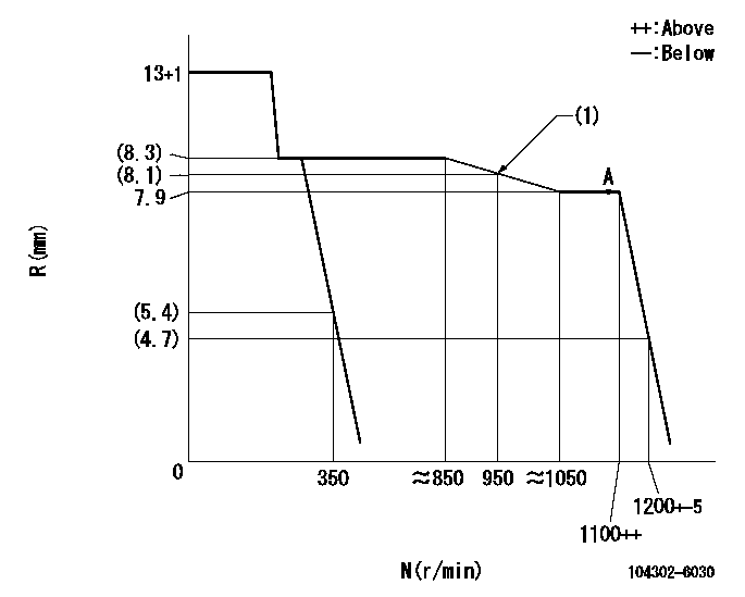
N:Pump speed
R:Rack position (mm)
(1)Apply the torque control spring so that the fuel injection quantity passes through this point.
----------
----------
----------
----------
Speed control lever angle
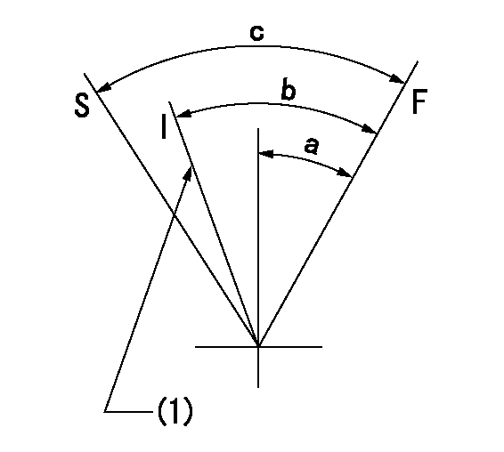
F:Full speed
I:Idle
S:Stop
(1)Set idling using the idle set spring.
----------
----------
a=27deg+-3deg b=28deg+-5deg c=(37deg)
----------
----------
a=27deg+-3deg b=28deg+-5deg c=(37deg)
Information:
Fill
Refer to the Cooling System Specifications for all information regarding acceptable water, coolant/antifreeze, and supplemental coolant additive requirements. Refer to the Refill Capacities chart in this publication for the capacity of your engine's system.8. Fill the system
Refer to the Cooling System Specifications for all information regarding acceptable water, coolant/antifreeze, and supplemental coolant additive requirements. Refer to the Refill Capacities chart in this publication for the capacity of your engine's system.8. Fill the system