Information injection-pump assembly
ZEXEL
104302-2030
1043022030
ISUZU
5156011310
5156011310

Rating:
Service parts 104302-2030 INJECTION-PUMP ASSEMBLY:
1.
_
2.
FUEL INJECTION PUMP
3.
GOVERNOR
5.
AUTOM. ADVANCE MECHANIS
6.
COUPLING PLATE
7.
COUPLING PLATE
8.
_
9.
_
11.
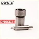
Nozzle and Holder
5-15300-110-2
12.
Open Pre:MPa(Kqf/cm2)
11.8{120}
15.
NOZZLE SET
Include in #1:
104302-2030
as INJECTION-PUMP ASSEMBLY
Cross reference number
ZEXEL
104302-2030
1043022030
ISUZU
5156011310
5156011310
Zexel num
Bosch num
Firm num
Name
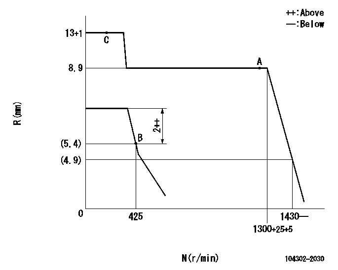
Calibration Data:
Adjustment conditions
Test oil
1404 Test oil ISO4113 or {SAEJ967d}
1404 Test oil ISO4113 or {SAEJ967d}
Test oil temperature
degC
40
40
45
Nozzle and nozzle holder
105780-8140
Bosch type code
EF8511/9A
Nozzle
105780-0000
Bosch type code
DN12SD12T
Nozzle holder
105780-2080
Bosch type code
EF8511/9
Opening pressure
MPa
17.2
Opening pressure
kgf/cm2
175
Injection pipe
Outer diameter - inner diameter - length (mm) mm 6-2-600
Outer diameter - inner diameter - length (mm) mm 6-2-600
Tester oil delivery pressure
kPa
157
157
157
Tester oil delivery pressure
kgf/cm2
1.6
1.6
1.6
Direction of rotation (viewed from drive side)
Left L
Left L
Injection timing adjustment
Direction of rotation (viewed from drive side)
Left L
Left L
Injection order
1-2
Pre-stroke
mm
2.1
2.05
2.15
Beginning of injection position
Drive side NO.1
Drive side NO.1
Difference between angles 1
Cyl.1-2 deg. 270 269.5 270.5
Cyl.1-2 deg. 270 269.5 270.5
Injection quantity adjustment
Adjusting point
A
Rack position
8.9
Pump speed
r/min
1300
1300
1300
Average injection quantity
mm3/st.
33.3
32.3
34.3
Max. variation between cylinders
%
0
-2.5
2.5
Basic
*
Fixing the lever
*
Injection quantity adjustment_02
Adjusting point
B
Rack position
5.4+-0.5
Pump speed
r/min
425
425
425
Average injection quantity
mm3/st.
5.9
4.9
6.9
Max. variation between cylinders
%
0
-14
14
Fixing the lever
*
Test data Ex:
Governor adjustment

N:Pump speed
R:Rack position (mm)
----------
----------
----------
----------
Speed control lever angle

F:Full speed
I:Idle
(1)Stopper bolt setting
----------
----------
a=35deg+-6deg b=25deg+-3deg
----------
----------
a=35deg+-6deg b=25deg+-3deg
Timing setting

(1)Pump vertical direction
(2)Position of gear mark 'Z' at No 1 cylinder's beginning of injection
(3)B.T.D.C.: aa
(4)-
----------
aa=16deg
----------
a=(120deg)
----------
aa=16deg
----------
a=(120deg)
Information:
PARTS NEEDED
Qty
Part Number Description
5 2321794 HOSE - INJECTOR LEAK OFF PIPE
In order to allow equitable parts availability to all participating dealers, please limit your initial parts order to not exceed 1% of dealership population. This is an initial order recommendation only, and the ultimate responsibility for ordering the total number of parts needed to satisfy the program lies with the dealer.
ACTION REQUIRED
Refer to the attached Rework Procedure.
SERVICE CLAIM ALLOWANCES
Product smu/age whichever comes first Caterpillar Dealer Suggested Customer Suggested
Parts % Labor Hrs% Parts % Labor Hrs% Parts % Labor Hrs%
0-500 hrs,
0-60 mo 100.0% 100.0% 0.0% 0.0% 0.0% 0.0%
This is a 0.5-hour job
PARTS DISPOSITION
Handle the parts in accordance with your Warranty Bulletin on warranty parts handling.
Rework Procedure
Note: Ensure that all adjustments and repairs that are carried out to the fuel system are performed by authorized personnel that have the correct training. Before beginning ANY work on the fuel system, refer to the Operation and Maintenance Manual, "General Hazard Information" for safety information.
Refer to System Operation, Testing and Adjusting, "Cleanliness of Fuel System Components" for detailed information on the standards of cleanliness that must be observed during ALL work on the fuel system.
Note: Care must be taken to ensure that fluids are contained during performance of inspection, maintenance, testing, adjusting. and repair of the product. Be prepared to collect the fluid with suitable containers before opening any compartment or disassembling any component containing fluids. Dispose of all fluids according to local regulations and mandates.
Important Notes:
Before attempting any work on the fuel system ensure that the engine is cleaned of any dirt that might contaminate the fuel system. Clean up any spilt fuel before undertaking further work. Check there is adequate clearance around all low pressure lines, and that any clamps are in place and correctly orientated.
No attempt should be made to clean/flush filter elements for re-use. DO NOT PRE-FILL THE FILTERS. Fuel can be hot after engine/machine operation. Care must be taken to ensure hot fuel does not come in contact with exposed skin. Allow engine to cool before undertaking any work.
Fuel Tube Rework Procedure ? Before/After Failure
1. Open/remove the engine cover or hood. Refer to Image1.2.1.
2. View the top of the engine.
3. Identify the 2321794 Injector Leak Off Pipe. Refer to Image1.2.2.
4. Check for a fuel leak around the injector leak off pipe to injector spigot interface.
5. If a fuel leak or residue is present or the pipe shows signs of wear or damage; replace the 232-1794 Injector Leak Off Pipe.
6. Perform a function test to ensure the root cause of the leak has been rectified.
Image1.2.1
Image1.2.2
