Information injection-pump assembly
ZEXEL
103862-0330
1038620330
KOMATSU
6164711710
6164711710
Rating:
Cross reference number
ZEXEL
103862-0330
1038620330
KOMATSU
6164711710
6164711710
Zexel num
Bosch num
Firm num
Name
Calibration Data:
Adjustment conditions
Test oil
1404 Test oil ISO4113 or {SAEJ967d}
1404 Test oil ISO4113 or {SAEJ967d}
Test oil temperature
degC
40
40
45
Nozzle and nozzle holder
105780-8130
Bosch type code
EFEP215A
Nozzle
105780-0050
Bosch type code
DN6TD119NP1T
Nozzle holder
105780-2090
Bosch type code
EFEP215
Opening pressure
MPa
17.2
Opening pressure
kgf/cm2
175
Injection pipe
Outer diameter - inner diameter - length (mm) mm 8-4-1500
Outer diameter - inner diameter - length (mm) mm 8-4-1500
Overflow valve
131425-1920
Overflow valve opening pressure
kPa
206
172
240
Overflow valve opening pressure
kgf/cm2
2.1
1.75
2.45
Tester oil delivery pressure
kPa
157
157
157
Tester oil delivery pressure
kgf/cm2
1.6
1.6
1.6
Direction of rotation (viewed from drive side)
Left L
Left L
Injection timing adjustment
Direction of rotation (viewed from drive side)
Left L
Left L
Injection order
1-3-4-5-
6-2-7-8
Pre-stroke
mm
3.8
3.75
3.85
Beginning of injection position
Drive side NO.1
Drive side NO.1
Difference between angles 1
Cal 1-3 deg. 45 44.5 45.5
Cal 1-3 deg. 45 44.5 45.5
Difference between angles 2
Cal 1-4 deg. 77 76.5 77.5
Cal 1-4 deg. 77 76.5 77.5
Difference between angles 3
Cal 1-5 deg. 135 134.5 135.5
Cal 1-5 deg. 135 134.5 135.5
Difference between angles 4
Cal 1-6 deg. 167 166.5 167.5
Cal 1-6 deg. 167 166.5 167.5
Difference between angles 5
Cyl.1-2 deg. 212 211.5 212.5
Cyl.1-2 deg. 212 211.5 212.5
Difference between angles 6
Cal 1-7 deg. 269.5 269 270
Cal 1-7 deg. 269.5 269 270
Difference between angles 7
Cal 1-8 deg. 301.5 301 302
Cal 1-8 deg. 301.5 301 302
Injection quantity adjustment
Adjusting point
A
Rack position
16.1
Pump speed
r/min
900
900
900
Each cylinder's injection qty
mm3/st.
495
487.1
502.9
Basic
*
Fixing the lever
*
Injection quantity adjustment_02
Adjusting point
B
Rack position
7+-0.5
Pump speed
r/min
400
400
400
Average injection quantity
mm3/st.
49
44
54
Max. variation between cylinders
%
0
-14
14
Fixing the rack
*
Test data Ex:
Governor adjustment
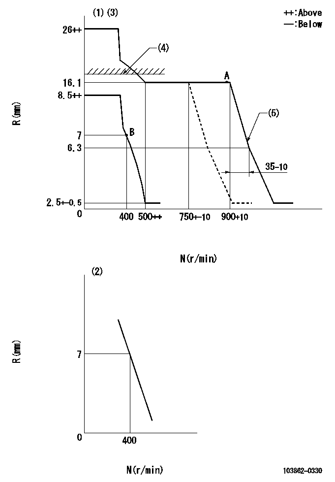
N:Pump speed
R:Rack position (mm)
(1)Minimum - maximum speed specification
(2)Variable speed specification: idling adjustment
(3)Target notch: K
(4)RACK LIMIT: RAL
(5)Idle sub spring setting: L1.
----------
K=(5) RAL=16.6+0.2mm L1=6.3-0.5mm
----------
----------
K=(5) RAL=16.6+0.2mm L1=6.3-0.5mm
----------
Speed control lever angle
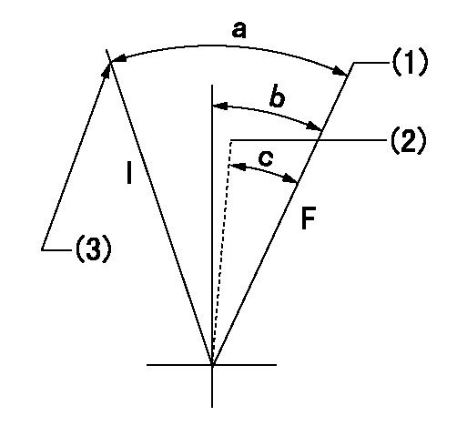
F:Full speed
I:Idle
(1)Speed set at aa (setting at shipping)
(2)Set the pump speed at bb.
(3)Stopper bolt setting
----------
aa=900r/min bb=750r/min
----------
a=37deg+-5deg b=14deg+-5deg c=12deg+-5deg
----------
aa=900r/min bb=750r/min
----------
a=37deg+-5deg b=14deg+-5deg c=12deg+-5deg
0000000901
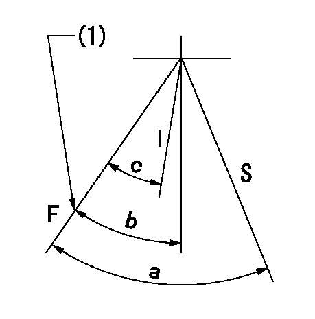
F:Full load
I:Idle
S:Stop
(1)The distance between the stopper bolt and the lever must be aa.
----------
aa=(0.8)mm
----------
a=40deg+-5deg b=25deg+-5deg c=(21deg)+-5deg
----------
aa=(0.8)mm
----------
a=40deg+-5deg b=25deg+-5deg c=(21deg)+-5deg
Timing setting

(1)Pump vertical direction
(2)Position of spline gear's aligning mark at No 1 cylinder's beginning of injection (key position)
(3)B.T.D.C.: aa
(4)-
----------
aa=36deg
----------
a=(130deg)
----------
aa=36deg
----------
a=(130deg)
Information:
To many, the diesel principle may not be new, however, the special features of Caterpillar Diesel Truck Engines require that the operator and the maintenance personnel become acquainted with the systems in order to give the engine the best possible care. Maximum service depends a great deal on a good maintenance schedule performed by reliable personnel with a basic understanding of the working principles and systems.Diesel Engine Principle
This diesel engine operates on the reciprocating piston 4-stroke cycle, compression ignition principle, and burns fuels commercially known as diesel fuels. The basic difference between the spark ignition engine and the diesel engine are; the method of introducing fuel into the system, and the method by which the fuel is ignited.The diesel engine always takes a full charge of "air only" on each inlet stroke, compresses it in an extremely small space causing the air to reach temperatures over 1000°F (537°C). Fuel is injected into the precombustion chamber as the piston nears the top of the compression stroke, where it mixes with the compressed air, and immediately starts to burn. This is called self-ignition, or spontaneous ignition. The expansion of the burning gases forces the piston down on a power stroke. Four Stroke Cycle Principle:
The four stroke cycle engine has separate strokes for each basic function. The four strokes and the order in which they occur are: Intake, compression, power and exhaust.It must be remembered that for the four stroke cycle to function, the inlet valves, exhaust valves, and fuel injection must be timed in proper sequence with the piston. This is accomplished by timing gears between the crankshaft, the valve train, and injection pumps. Intake Stroke: As the piston moves down on the inlet stroke the inlet valves are opened and exhaust valves are closed by the camshaft and rocker arm arrangement. Air is drawn in through the air cleaner by the turbocharger and forced through the water cooled aftercooler and then charges the cylinder through the intake valves. Compression Stroke: At the end of the intake stroke both inlet valves close and the exhaust valves remain closed. As the