Information injection-pump assembly
ZEXEL
103862-0322
1038620322
Rating:
Cross reference number
ZEXEL
103862-0322
1038620322
Zexel num
Bosch num
Firm num
Name
Calibration Data:
Adjustment conditions
Test oil
1404 Test oil ISO4113 or {SAEJ967d}
1404 Test oil ISO4113 or {SAEJ967d}
Test oil temperature
degC
40
40
45
Nozzle and nozzle holder
105780-8130
Bosch type code
EFEP215A
Nozzle
105780-0050
Bosch type code
DN6TD119NP1T
Nozzle holder
105780-2090
Bosch type code
EFEP215
Opening pressure
MPa
17.2
Opening pressure
kgf/cm2
175
Injection pipe
Outer diameter - inner diameter - length (mm) mm 8-4-1500
Outer diameter - inner diameter - length (mm) mm 8-4-1500
Overflow valve
131425-1920
Overflow valve opening pressure
kPa
206
172
240
Overflow valve opening pressure
kgf/cm2
2.1
1.75
2.45
Tester oil delivery pressure
kPa
157
157
157
Tester oil delivery pressure
kgf/cm2
1.6
1.6
1.6
Direction of rotation (viewed from drive side)
Left L
Left L
Injection timing adjustment
Direction of rotation (viewed from drive side)
Left L
Left L
Injection order
1-3-4-5-
6-2-7-8
Pre-stroke
mm
3.8
3.75
3.85
Beginning of injection position
Drive side NO.1
Drive side NO.1
Difference between angles 1
Cal 1-3 deg. 45 44.5 45.5
Cal 1-3 deg. 45 44.5 45.5
Difference between angles 2
Cal 1-4 deg. 77 76.5 77.5
Cal 1-4 deg. 77 76.5 77.5
Difference between angles 3
Cal 1-5 deg. 135 134.5 135.5
Cal 1-5 deg. 135 134.5 135.5
Difference between angles 4
Cal 1-6 deg. 167 166.5 167.5
Cal 1-6 deg. 167 166.5 167.5
Difference between angles 5
Cyl.1-2 deg. 212 211.5 212.5
Cyl.1-2 deg. 212 211.5 212.5
Difference between angles 6
Cal 1-7 deg. 269.5 269 270
Cal 1-7 deg. 269.5 269 270
Difference between angles 7
Cal 1-8 deg. 301.5 301 302
Cal 1-8 deg. 301.5 301 302
Injection quantity adjustment
Adjusting point
A
Rack position
13.7
Pump speed
r/min
1000
1000
1000
Each cylinder's injection qty
mm3/st.
400
393.6
406.4
Basic
*
Fixing the lever
*
Boost pressure
kPa
37.3
37.3
Boost pressure
mmHg
280
280
Injection quantity adjustment_02
Adjusting point
B
Rack position
7.9+-0.5
Pump speed
r/min
300
300
300
Average injection quantity
mm3/st.
60
55
65
Max. variation between cylinders
%
0
-14
14
Fixing the rack
*
Boost pressure
kPa
0
0
0
Boost pressure
mmHg
0
0
0
Boost compensator adjustment
Pump speed
r/min
500
500
500
Rack position
13.4
Boost pressure
kPa
10.7
8
13.4
Boost pressure
mmHg
80
60
100
Boost compensator adjustment_02
Pump speed
r/min
500
500
500
Rack position
15
Boost pressure
kPa
29.3
25.3
33.3
Boost pressure
mmHg
220
190
250
Test data Ex:
Governor adjustment
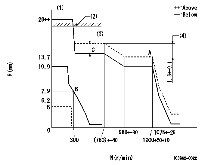
N:Pump speed
R:Rack position (mm)
(1)Target notch: K
(2)RACK LIMIT: RAL
(3)Boost compensator stroke: BCL
(4)Rack difference between N = N1 and N = N2
----------
K=(15) RAL=15.5+0.2mm BCL=1.6+-0.1mm N1=1000r/min N2=700r/min
----------
----------
K=(15) RAL=15.5+0.2mm BCL=1.6+-0.1mm N1=1000r/min N2=700r/min
----------
Speed control lever angle
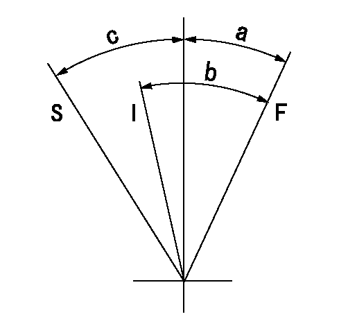
F:Full speed
I:Idle
S:Stop
----------
----------
a=(22deg)+-5deg b=(38deg)+-5deg c=30deg+-5deg
----------
----------
a=(22deg)+-5deg b=(38deg)+-5deg c=30deg+-5deg
Stop lever angle
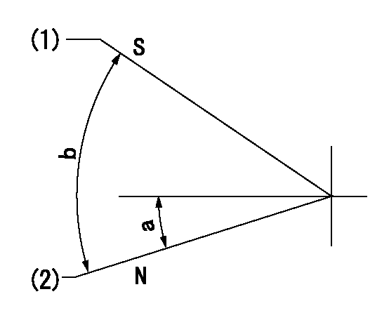
N:Pump normal
S:Stop the pump.
(1)Set the stopper bolt at rack position = aa, speed = bb.
(2)Clearance between stopper bolt and lever must be cc.
----------
aa=5mm bb=100r/min cc=2+1mm
----------
a=16deg+-5deg b=40deg+-5deg
----------
aa=5mm bb=100r/min cc=2+1mm
----------
a=16deg+-5deg b=40deg+-5deg
Timing setting

(1)Pump vertical direction
(2)Position of spline gear's aligning mark at No 1 cylinder's beginning of injection (key position)
(3)B.T.D.C.: aa
(4)-
----------
aa=36deg
----------
a=(130deg)
----------
aa=36deg
----------
a=(130deg)
Information:
A starting motor solenoid that will not operate may not be receiving battery current. Attach one lead of the voltmeter to the solenoid battery cable connection. Ground the other lead. No voltmeter reading indicates a faulty circuit from the battery. A voltmeter reading indicates further testing is necessary. Continue the test by attaching one voltmeter lead to the starting motor solenoid small wire terminal and the other lead to ground. Observe the voltmeter and turn the HEAT-START switch to START. A voltmeter reading indicates that the malfunction is in the solenoid. No voltmeter reading indicates that either the series-parallel switch is the fault or the HEAT-START switch does not close when turned to the START position. Attach one lead of the voltmeter to the HEAT-START switch battery wire terminal and ground the other lead. A voltmeter reading indicates a defective switch. No voltmeter reading indicates further testing of the series-parallel switch is necessary. A starting motor that operates too slow can be overloaded by excessive mechanical friction within the engine being started. Slow starting motor operation can also be caused by shorts, loose connections and/or excessive dirt within the motor. PINION CLEARANCE ADJUSTMENT: Whenever the solenoid is installed, the pinion clearance should be adjusted. The adjustment should be made with the starting motor removed.Bench test and adjust the pinion clearance at installation of solenoid as follows:
CIRCUIT FOR CHECKING AND ADJUSTING PINION CLEARANCE1. Install the solenoid without connector from the MOTOR terminal on solenoid to the motor.2. Connect a battery, of the same voltage as the solenoid, to the terminal marked SW.3. Connect the other side of battery to ground terminal or to solenoid frame.
CHECKING PINION CLEARANCE
ADJUSTING PINION CLEARANCE4. MOMENTARILY flash a jumper wire from the solenoid terminal marked MOTOR to the frame or ground terminal. The pinion will shift into cranking position and will remain there until the battery is disconnected.5. Push pinion towards commutator end to eliminate free movement.6. Pinion clearance should be .36 in. (9,14 mm).7. Adjust clearance by removing plug and turning shaft nut.General Reconditioning
Approximately every 200,000 miles, the starter should be removed so that it may be completely disassembled, washed and have all parts replaced that show evidence of being unsatisfactory for reason of wear. Do not use a degreaser or high temperature cleaning method when cleaning parts of the starter.No periodic service is indicated for the electric starter brushes between general reconditioning periods. The brushes should only be inspected after removal of the starter from the engine and removal of the commutator end bearing frame. The electric starter commutator end and drive end bearings are equipped with wicks for lubrication purposes. The wicks should be saturated with oil whenever the electric starter is removed or disassembled. It is suggested that cleaning and reconditioning be entrusted to your authorized dealer.Glow Plugs
TESTING GLOW PLUGS: Glow plugs can be checked with an ammeter. Disconnect the wire lead from the glow plug terminal on the HEAT-START switch. Install an ammeter, in series, between the disconnected lead and