Information injection-pump assembly
ZEXEL
103862-0320
1038620320

Rating:
Service parts 103862-0320 INJECTION-PUMP ASSEMBLY:
1.
_
3.
GOVERNOR
6.
COUPLING PLATE
7.
COUPLING PLATE
8.
_
9.
_
11.
Nozzle and Holder
6162-12-3403
12.
Open Pre:MPa(Kqf/cm2)
29.4{300}
15.
NOZZLE SET
Cross reference number
ZEXEL
103862-0320
1038620320
Zexel num
Bosch num
Firm num
Name
Calibration Data:
Adjustment conditions
Test oil
1404 Test oil ISO4113 or {SAEJ967d}
1404 Test oil ISO4113 or {SAEJ967d}
Test oil temperature
degC
40
40
45
Nozzle and nozzle holder
105780-8130
Bosch type code
EFEP215A
Nozzle
105780-0050
Bosch type code
DN6TD119NP1T
Nozzle holder
105780-2090
Bosch type code
EFEP215
Opening pressure
MPa
17.2
Opening pressure
kgf/cm2
175
Injection pipe
Outer diameter - inner diameter - length (mm) mm 8-4-1500
Outer diameter - inner diameter - length (mm) mm 8-4-1500
Overflow valve
131424-6620
Overflow valve opening pressure
kPa
206
172
240
Overflow valve opening pressure
kgf/cm2
2.1
1.75
2.45
Tester oil delivery pressure
kPa
157
157
157
Tester oil delivery pressure
kgf/cm2
1.6
1.6
1.6
Direction of rotation (viewed from drive side)
Left L
Left L
Injection timing adjustment
Direction of rotation (viewed from drive side)
Left L
Left L
Injection order
1-3-4-5-
6-2-7-8
Pre-stroke
mm
3.8
3.75
3.85
Beginning of injection position
Drive side NO.1
Drive side NO.1
Difference between angles 1
Cal 1-3 deg. 45 44.5 45.5
Cal 1-3 deg. 45 44.5 45.5
Difference between angles 2
Cal 1-4 deg. 77 76.5 77.5
Cal 1-4 deg. 77 76.5 77.5
Difference between angles 3
Cal 1-5 deg. 135 134.5 135.5
Cal 1-5 deg. 135 134.5 135.5
Difference between angles 4
Cal 1-6 deg. 167 166.5 167.5
Cal 1-6 deg. 167 166.5 167.5
Difference between angles 5
Cyl.1-2 deg. 212 211.5 212.5
Cyl.1-2 deg. 212 211.5 212.5
Difference between angles 6
Cal 1-7 deg. 269.5 269 270
Cal 1-7 deg. 269.5 269 270
Difference between angles 7
Cal 1-8 deg. 301.5 301 302
Cal 1-8 deg. 301.5 301 302
Injection quantity adjustment
Adjusting point
A
Rack position
14
Pump speed
r/min
1000
1000
1000
Each cylinder's injection qty
mm3/st.
413
406.4
419.6
Basic
*
Fixing the lever
*
Boost pressure
kPa
30.7
30.7
Boost pressure
mmHg
230
230
Injection quantity adjustment_02
Adjusting point
B
Rack position
7.9+-0.5
Pump speed
r/min
300
300
300
Average injection quantity
mm3/st.
60
55
65
Max. variation between cylinders
%
0
-14
14
Fixing the rack
*
Boost pressure
kPa
0
0
0
Boost pressure
mmHg
0
0
0
Boost compensator adjustment
Pump speed
r/min
500
500
500
Rack position
14
Boost pressure
kPa
4
1.3
6.7
Boost pressure
mmHg
30
10
50
Boost compensator adjustment_02
Pump speed
r/min
500
500
500
Rack position
15.4
Boost pressure
kPa
20
16
24
Boost pressure
mmHg
150
120
180
Test data Ex:
Governor adjustment
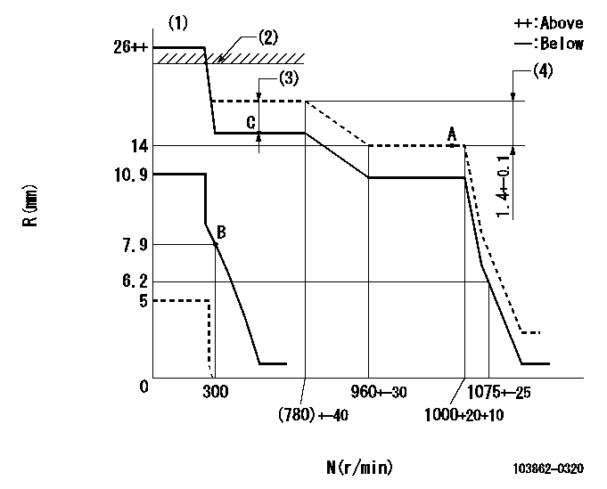
N:Pump speed
R:Rack position (mm)
(1)Target notch: K
(2)RACK LIMIT: RAL
(3)Boost compensator stroke: BCL
(4)Rack difference between N = N1 and N = N2
----------
K=(15) RAL=15.9+0.2mm BCL=1.4+-0.1mm N1=1000r/min N2=700r/min
----------
----------
K=(15) RAL=15.9+0.2mm BCL=1.4+-0.1mm N1=1000r/min N2=700r/min
----------
Speed control lever angle
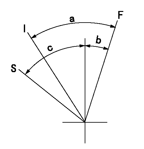
F:Full speed
I:Idle
S:Stop
----------
----------
a=(40deg)+-5deg b=(30deg)+-5deg c=30deg+-5deg
----------
----------
a=(40deg)+-5deg b=(30deg)+-5deg c=30deg+-5deg
Stop lever angle
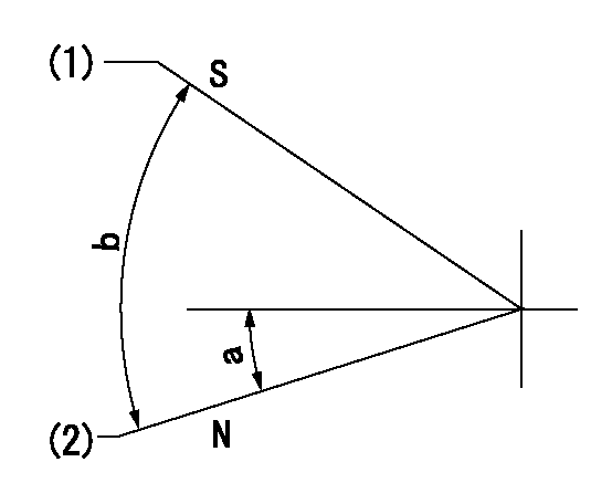
N:Pump normal
S:Stop the pump.
(1)Set the stopper bolt at rack position = aa, speed = bb.
(2)Clearance between stopper bolt and lever must be cc.
----------
aa=5mm bb=100r/min cc=2+1mm
----------
a=16deg+-5deg b=40deg+-5deg
----------
aa=5mm bb=100r/min cc=2+1mm
----------
a=16deg+-5deg b=40deg+-5deg
Timing setting

(1)Pump vertical direction
(2)Position of spline gear's aligning mark at No 1 cylinder's beginning of injection (key position)
(3)B.T.D.C.: aa
(4)-
----------
aa=36deg
----------
a=(130deg)
----------
aa=36deg
----------
a=(130deg)
Information:
PRIMARY FUEL FILTERFINAL FUEL FILTER ELEMENT: The filter element collects and holds contaminants and cannot be washed or otherwise restored. To remove the used filter element, proceed as follows:1. Stop the engine and close the diesel fuel line valve (if equipped).2. Unscrew and remove filter.3. Clean the gasket sealing surface on the filter base.
Do not pour fuel into the new filter elements before installing. Prime the system as instructed in the topic, PRIMING THE FUEL SYSTEM.
4. Lubricate the filter gasket with clean diesel fuel.5. Tighten the filter by hand, only tight enough to prevent leaks. (Do not overtighten.)6. Prime the fuel system. Refer to the topic "PRIMING THE FUEL SYSTEM"
REMOVING FUEL FILTER ELEMENT KEEP A NEW FUEL FILTER ON HAND: An extra filter should be kept on hand for replacement. Always keep the filter wrapped in its original carton to insure against dust and dirt accumulation which will shorten the life of the filter or may cause damage to the fuel injection equipment.PRIMING THE FUEL SYSTEM: Any time the fuel flow is broken and air is allowed to get into the fuel system, the system must be primed. If air is left in the lines, the fuel system may become air bound, resulting in inability to start the engine or the misfiring of one or more cylinders.
PRIMING THE FUEL SYSTEMThe fuel priming pump is mounted on the fuel filter housing as shown. If only the fuel filter is changed follow steps 1 through 5. If the fuel system is completely drained or if the engine has run out of fuel continue with steps through 10.1. Check to see that the fuel line valve is open.2. Open the fuel filter vent valve on the fuel filter housing.3. Loosen the knob of the fuel priming pump.4. Operate the pump plunger in and out until the flow of fuel from the vent valve is continuous and free of air bubbles.5. Close vent valve.6. Move governor control to the shut-off position and loosen fuel line nuts (one at a time) at the pump housing.7. Operate priming pump until clear fuel flows from the fuel pump lines. Tighten fuel line nut.8. Repeat for each fuel pump.9. Lock the knob of the fuel priming pump to its original position.10. Start the engine. If the engine does not run smoothly further bleeding may be necessary. With the engine running, open and close the fuel injection line nuts, one at a time, several times in succession to be sure all the air is bled from the system. Tighten fuel line nuts to 30 lbs.ft. (4,1 mkg). Do not overtighten.Fuel Injection Equipment
When improper fuel injection is affecting engine operation, a systematic check should be made to determine the cause. The most likely cause is dirt or water in the fuel. Drain the sediment from the fuel tank. Check the fuel pressure gauge as mentioned in the topic, FUEL FILTERING SYSTEM. Replace the filter element if necessary. Then prime the fuel system until clean fuel reaches the fuel