Information injection-pump assembly
BOSCH
9 400 616 379
9400616379
ZEXEL
103860-0031
1038600031
KOMATSU
6164711510
6164711510
Rating:
Service parts 103860-0031 INJECTION-PUMP ASSEMBLY:
1.
_
4.
SUPPLY PUMP
6.
COUPLING PLATE
7.
COUPLING PLATE
8.
_
9.
_
11.
Nozzle and Holder
6162-12-3403
12.
Open Pre:MPa(Kqf/cm2)
29.4{300}
15.
NOZZLE SET
Cross reference number
BOSCH
9 400 616 379
9400616379
ZEXEL
103860-0031
1038600031
KOMATSU
6164711510
6164711510
Zexel num
Bosch num
Firm num
Name
Calibration Data:
Adjustment conditions
Test oil
1404 Test oil ISO4113 or {SAEJ967d}
1404 Test oil ISO4113 or {SAEJ967d}
Test oil temperature
degC
40
40
45
Nozzle and nozzle holder
105780-8130
Bosch type code
EFEP215A
Nozzle
105780-0050
Bosch type code
DN6TD119NP1T
Nozzle holder
105780-2090
Bosch type code
EFEP215
Opening pressure
MPa
17.2
Opening pressure
kgf/cm2
175
Injection pipe
Outer diameter - inner diameter - length (mm) mm 8-4-1500
Outer diameter - inner diameter - length (mm) mm 8-4-1500
Overflow valve
131425-1920
Overflow valve opening pressure
kPa
206
172
240
Overflow valve opening pressure
kgf/cm2
2.1
1.75
2.45
Tester oil delivery pressure
kPa
157
157
157
Tester oil delivery pressure
kgf/cm2
1.6
1.6
1.6
Direction of rotation (viewed from drive side)
Left L
Left L
Injection timing adjustment
Direction of rotation (viewed from drive side)
Left L
Left L
Injection order
1-3-4-5-
6-2-7-8
Pre-stroke
mm
3.8
3.75
3.85
Beginning of injection position
Drive side NO.1
Drive side NO.1
Difference between angles 1
Cal 1-3 deg. 45 44.5 45.5
Cal 1-3 deg. 45 44.5 45.5
Difference between angles 2
Cal 1-4 deg. 77 76.5 77.5
Cal 1-4 deg. 77 76.5 77.5
Difference between angles 3
Cal 1-5 deg. 135 134.5 135.5
Cal 1-5 deg. 135 134.5 135.5
Difference between angles 4
Cal 1-6 deg. 167 166.5 167.5
Cal 1-6 deg. 167 166.5 167.5
Difference between angles 5
Cyl.1-2 deg. 212 211.5 212.5
Cyl.1-2 deg. 212 211.5 212.5
Difference between angles 6
Cal 1-7 deg. 269.5 269 270
Cal 1-7 deg. 269.5 269 270
Difference between angles 7
Cal 1-8 deg. 301.5 301 302
Cal 1-8 deg. 301.5 301 302
Injection quantity adjustment
Adjusting point
A
Rack position
15.2
Pump speed
r/min
1050
1050
1050
Each cylinder's injection qty
mm3/st.
470
462.5
477.5
Basic
*
Fixing the lever
*
Boost pressure
kPa
61.3
61.3
Boost pressure
mmHg
460
460
Injection quantity adjustment_02
Adjusting point
B
Rack position
7.9+-0.5
Pump speed
r/min
300
300
300
Average injection quantity
mm3/st.
60
55
65
Max. variation between cylinders
%
0
-14
14
Fixing the rack
*
Boost pressure
kPa
0
0
0
Boost pressure
mmHg
0
0
0
Boost compensator adjustment
Pump speed
r/min
500
500
500
Rack position
13.3
Boost pressure
kPa
26
25.3
26.7
Boost pressure
mmHg
195
190
200
Boost compensator adjustment_02
Pump speed
r/min
500
500
500
Rack position
15.2
Boost pressure
kPa
48
41.3
54.7
Boost pressure
mmHg
360
310
410
Test data Ex:
Governor adjustment

N:Pump speed
R:Rack position (mm)
(1)Target notch: K
(2)RACK LIMIT: RAL
(3)Boost compensator stroke: BCL
----------
K=(15) RAL=15.7+0.2mm BCL=1.9+-0.1mm
----------
----------
K=(15) RAL=15.7+0.2mm BCL=1.9+-0.1mm
----------
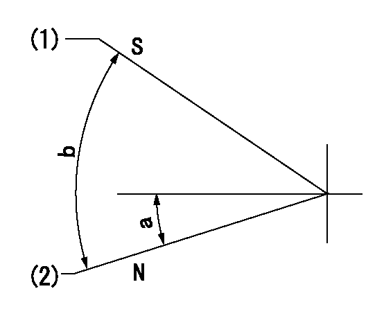
Speed control lever angle

F:Full speed
I:Idle
(1)Stopper bolt setting
----------
----------
a=(40deg)+-5deg b=(30deg)+-5deg
----------
----------
a=(40deg)+-5deg b=(30deg)+-5deg
Stop lever angle
N:Pump normal
S:Stop the pump.
(1)Set the stopper bolt at rack position = aa, speed = bb.
(2)Clearance between stopper bolt and lever must be cc.
----------
aa=5mm bb=100r/min cc=2+1mm
----------
a=16deg+-5deg b=40deg+-5deg
----------
aa=5mm bb=100r/min cc=2+1mm
----------
a=16deg+-5deg b=40deg+-5deg
Timing setting

(1)Pump vertical direction
(2)Position of spline gear's aligning mark at No 1 cylinder's beginning of injection (key position)
(3)B.T.D.C.: aa
(4)-
----------
aa=36deg
----------
a=(130deg)
----------
aa=36deg
----------
a=(130deg)
Information:
Table 2
Specifications for Pressure Loss
Direct Injection Fuel Systems
Nozzle pressure must not drop below a gauge reading of
3450 kPa (500 psi) during a 5 second time interval.
Nozzle pressure must drop below a gauge reading of
1380 kPa (200 psi) after an additional 25 second time interval. (1)
( 1 ) A gauge reading of 0 kPa (0 psi) is acceptable after the first 5 second time interval has elapsed.
Illustration 3 g00923167
If the fuel nozzle is not within specifications, stop the test and do not use the fuel nozzle.Valve Opening Pressure Test
Slowly increase the pressure until fluid begins to flow from the tip of the fuel nozzle. Record this pressure as the VOP of the fuel nozzle.
Compare the test results to the specifications for the type of fuel nozzle that is being tested. Refer to Table 3, or Table 4.For precombustion chamber fuel systems, use these specifications:
Table 3
Specifications for Valve Opening Pressure
Precombustion Chamber Fuel Systems
2760 to 5170 kPa (400 to 750 psi)
Illustration 4 g00934108
If the VOP is not within specifications, stop the test and do not use the fuel nozzle.For direct injection fuel systems, use these specifications:
Table 4
Specifications for Valve Opening Pressure
Direct Injection Fuel Systems
16500 to 21400 kPa (2400 to 3100 psi)
Illustration 5 g00923174
If the VOP is not within specifications, stop the test and do not use the fuel nozzle.Tip Leakage Test (Direct Injection Fuel Systems)
Note: Fuel nozzles for precombustion chamber fuel systems can not be tested for tip leakage accurately. Do not perform this test on fuel nozzles for a precombustion