Information injection-pump assembly
ZEXEL
103682-0523
1036820523
Rating:
Cross reference number
ZEXEL
103682-0523
1036820523
Zexel num
Bosch num
Firm num
Name
103682-0523
INJECTION-PUMP ASSEMBLY
14BS PE4-8Z PE
14BS PE4-8Z PE
Calibration Data:
Adjustment conditions
Test oil
1404 Test oil ISO4113 or {SAEJ967d}
1404 Test oil ISO4113 or {SAEJ967d}
Test oil temperature
degC
40
40
45
Nozzle and nozzle holder
105780-8130
Bosch type code
EFEP215A
Nozzle
105780-0050
Bosch type code
DN6TD119NP1T
Nozzle holder
105780-2090
Bosch type code
EFEP215
Opening pressure
MPa
17.2
Opening pressure
kgf/cm2
175
Injection pipe
Outer diameter - inner diameter - length (mm) mm 8-4-1500
Outer diameter - inner diameter - length (mm) mm 8-4-1500
Overflow valve
131425-1620
Overflow valve opening pressure
kPa
255
221
289
Overflow valve opening pressure
kgf/cm2
2.6
2.25
2.95
Tester oil delivery pressure
kPa
255
255
255
Tester oil delivery pressure
kgf/cm2
2.6
2.6
2.6
RED3 control unit part number
407910-2
470
RED3 rack sensor specifications
mm
15
Direction of rotation (viewed from drive side)
Left L
Left L
Injection timing adjustment
Direction of rotation (viewed from drive side)
Left L
Left L
Injection order
1-5-3-6-
2-4
Pre-stroke
mm
3
2.95
3.05
Beginning of injection position
Drive side NO.1
Drive side NO.1
Difference between angles 1
Cal 1-5 deg. 60 59.5 60.5
Cal 1-5 deg. 60 59.5 60.5
Difference between angles 2
Cal 1-3 deg. 120 119.5 120.5
Cal 1-3 deg. 120 119.5 120.5
Difference between angles 3
Cal 1-6 deg. 180 179.5 180.5
Cal 1-6 deg. 180 179.5 180.5
Difference between angles 4
Cyl.1-2 deg. 240 239.5 240.5
Cyl.1-2 deg. 240 239.5 240.5
Difference between angles 5
Cal 1-4 deg. 300 299.5 300.5
Cal 1-4 deg. 300 299.5 300.5
Injection quantity adjustment
Rack position
(12.8)
Vist
V
1.44
1.44
1.44
Pump speed
r/min
900
900
900
Average injection quantity
mm3/st.
733
726
740
Max. variation between cylinders
%
0
-4
4
Basic
*
Remarks
Same Vista as row R (103682-0534)
Same Vista as row R (103682-0534)
Injection quantity adjustment_02
Rack position
(5.6)
Vist
V
2.9
2.8
3
Pump speed
r/min
340
340
340
Average injection quantity
mm3/st.
43.5
38.5
48.5
Max. variation between cylinders
%
0
-14
14
Test data Ex:
Speed control lever angle
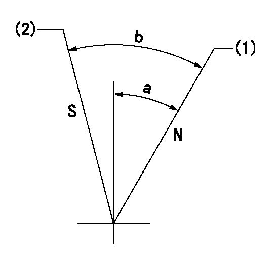
N:Pump normal
S:Stop the pump.
(1)Rack position = aa
(2)Rack position bb
----------
aa=16mm bb=1mm
----------
a=29deg+-5deg b=39deg+-5deg
----------
aa=16mm bb=1mm
----------
a=29deg+-5deg b=39deg+-5deg
0000000901
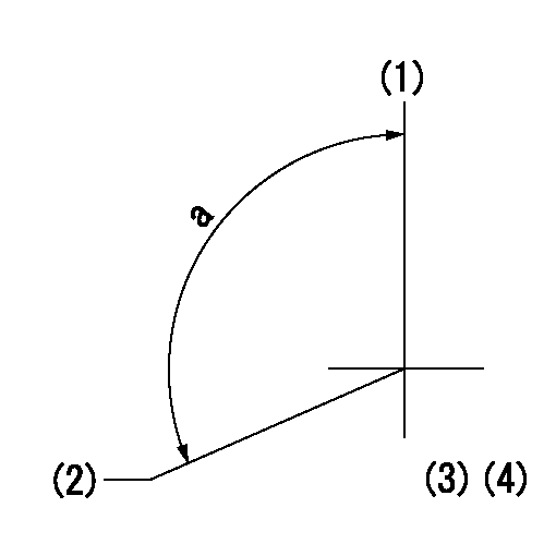
(1)Pump vertical direction
(2)Coupling's key groove position at No 1 cylinder's beginning of injection
(3)B.T.D.C.: aa
(4)-
----------
aa=25deg
----------
a=(120deg)
----------
aa=25deg
----------
a=(120deg)
Stop lever angle

(Rs) rack sensor specifications
(C/U) control unit part number
(V) Rack sensor output voltage
(R) Rack position (mm)
1. Confirming governor output characteristics (rack 15 mm, span 6 mm)
(1)When the output voltages of the rack sensor are V1 and V2, check that the rack positions R1 and R2 in the table above are satisfied.
----------
----------
----------
----------
Information:
Introduction
This Special Instruction provides detailed instructions on the installation of the sleeve into the compensator group of the 3408E and 3412E Unit Injector Hydraulic Pump. If leaks are experienced at the joint of the compensator and the adapter block, the 174-8943 Sleeve may be installed to improve sealing. The new press fit sleeve contains the O-ring more securely than the original slip fit sleeve.Note: Engines built prior to the serial number break that contain the new sleeve have a "S" stamped at the end of the part number on the serial number plate of the pump. The reworked part numbers appear as "144-0835-06S". Individual Components
Table 1
Quantity Part Number Part Description
1 174-8943 Sleeve
1 135-2652 O-Ring
1 033-6039 O-Ring
6 9X-7680 O-Ring Necessary Tools
One of the following tools may be used to insert the new sleeve into the compensator group.
A 31.750 mm (1.250 inch) diameter flat plate.
The 1P-0467 Drive Plate from 1P-0510 Driver Group .
An acceptable bearing insertion tool.Removal Of The O-Ring Seals
Illustration 1 g00638376
Remove the four bolts (1) from the compensator (2). Remove the compensator and the adapter. Do not adjust the compensator. Refer to Special Instruction, REHS0192-03, step 3 of procedure for "Disassembly of the 144-0835 Unit Injector Hydraulic Pump Group ".
Illustration 2 g00638368
Remove the four O-ring seals (3) from the bottom side of the adapter. Refer to Special Instruction, REHS0192-03, step 4 of procedure for "Disassembly of the 144-0835 Unit Injector Hydraulic Pump Group ".
Illustration 3 g00638372
Remove the four O-ring seals (4) from the two housings. Refer to Special Instruction, REHS0192-03, step 5 of procedure for "Disassembly of the 144-0835 Unit Injector Hydraulic Pump Group ".
Remove the slip fit sleeve from the compensator housing.Installation Of The Sleeve
Illustration 4 g00637918
(1) Compensator assembly. (2) 174-8943 Sleeve .
Invert the compensator assembly (1). Hold the compensator assembly securely within a vise or a press table.
Start the sleeve (2) by hand into the compensator assembly (1) .Note: It is important that the groove on the outside diameter of the sleeve is oriented toward the O-ring in the joint. If this is not done, there will not be sufficient room to properly seal the O-ring.
Press the sleeve (2) flush with the surface of the compensator assembly (1) using the 1P-0467 Drive Plate or by using an acceptable bearing insertion tool.Installation Of The O-Ring Seals
Illustration 5 g00638368
Install the four O-ring seals (3) on the bottom side of the adapter. Refer to Special Instruction, REHS0192-03, step 16 of procedure for "Assembly of the 144-0835 Unit Injector Hydraulic Pump Group ".
Illustration 6 g00638372
Install the four O-rings (4) on the two housings. Refer to Special Instruction, REHS0192-03, step 17 of procedure for "Assembly of the 144-0835 Unit Injector Hydraulic Pump Group ".
Illustration 7 g00638376
Install the compensator assembly (2) and the adapter as a unit vertically so that the O-rings seals are not damaged. Tighten the four bolts (1) to the following torque.Torque for bolts ... 8 1 N
Have questions with 103682-0523?
Group cross 103682-0523 ZEXEL
Komatsu
103682-0523
INJECTION-PUMP ASSEMBLY