Information injection-pump assembly
ZEXEL
103682-0500
1036820500
Rating:
Service parts 103682-0500 INJECTION-PUMP ASSEMBLY:
1.
_
5.
AUTOM. ADVANCE MECHANIS
6.
COUPLING PLATE
7.
COUPLING PLATE
8.
_
9.
_
10.
NOZZLE AND HOLDER ASSY
11.
Nozzle and Holder
12.
Open Pre:MPa(Kqf/cm2)
13.
NOZZLE-HOLDER
14.
NOZZLE
15.
NOZZLE SET
Cross reference number
ZEXEL
103682-0500
1036820500
Zexel num
Bosch num
Firm num
Name
Calibration Data:
Adjustment conditions
Test oil
1404 Test oil ISO4113 or {SAEJ967d}
1404 Test oil ISO4113 or {SAEJ967d}
Test oil temperature
degC
40
40
45
Nozzle and nozzle holder
105780-8130
Bosch type code
EFEP215A
Nozzle
105780-0050
Bosch type code
DN6TD119NP1T
Nozzle holder
105780-2090
Bosch type code
EFEP215
Opening pressure
MPa
17.2
Opening pressure
kgf/cm2
175
Injection pipe
Outer diameter - inner diameter - length (mm) mm 8-4-1500
Outer diameter - inner diameter - length (mm) mm 8-4-1500
Overflow valve
131424-1420
Overflow valve opening pressure
kPa
157
123
191
Overflow valve opening pressure
kgf/cm2
1.6
1.25
1.95
Tester oil delivery pressure
kPa
157
157
157
Tester oil delivery pressure
kgf/cm2
1.6
1.6
1.6
Direction of rotation (viewed from drive side)
Left L
Left L
Injection timing adjustment
Direction of rotation (viewed from drive side)
Left L
Left L
Injection order
1-4-2-6-
3-5
Pre-stroke
mm
4.5
4.45
4.55
Beginning of injection position
Governor side NO.1
Governor side NO.1
Difference between angles 1
Cal 1-4 deg. 60 59.5 60.5
Cal 1-4 deg. 60 59.5 60.5
Difference between angles 2
Cyl.1-2 deg. 120 119.5 120.5
Cyl.1-2 deg. 120 119.5 120.5
Difference between angles 3
Cal 1-6 deg. 180 179.5 180.5
Cal 1-6 deg. 180 179.5 180.5
Difference between angles 4
Cal 1-3 deg. 240 239.5 240.5
Cal 1-3 deg. 240 239.5 240.5
Difference between angles 5
Cal 1-5 deg. 300 299.5 300.5
Cal 1-5 deg. 300 299.5 300.5
Injection quantity adjustment
Adjusting point
A
Rack position
19.6
Pump speed
r/min
600
600
600
Average injection quantity
mm3/st.
777
762
792
Max. variation between cylinders
%
0
-3
3
Basic
*
Fixing the rack
*
Injection quantity adjustment_02
Adjusting point
B
Rack position
7
Pump speed
r/min
640
630
640
Average injection quantity
mm3/st.
90.5
85.2
95.8
Max. variation between cylinders
%
0
-10
10
Fixing the rack
*
Injection quantity adjustment_03
Adjusting point
C
Rack position
20.7
Pump speed
r/min
600
600
600
Average injection quantity
mm3/st.
841
821
861
Fixing the rack
*
Injection quantity adjustment_04
Adjusting point
D
Rack position
9.3+-0.5
Pump speed
r/min
250
250
250
Average injection quantity
mm3/st.
100
90
110
Fixing the rack
*
Injection quantity adjustment_05
Adjusting point
E
Rack position
21.7+0.5
Pump speed
r/min
100
100
100
Average injection quantity
mm3/st.
770
770
830
Fixing the lever
*
Rack limit
*
Test data Ex:
Governor adjustment
N:Pump speed
R:Rack position (mm)
(1)Target notch: K
(2)Delivered with idle spring not operating.
(3)RACK LIMIT: RAL
(4)Idle sub spring setting: L1.
----------
K=25 RAL=21.7+0.5mm L1=7-0.5mm
----------
----------
K=25 RAL=21.7+0.5mm L1=7-0.5mm
----------
Speed control lever angle
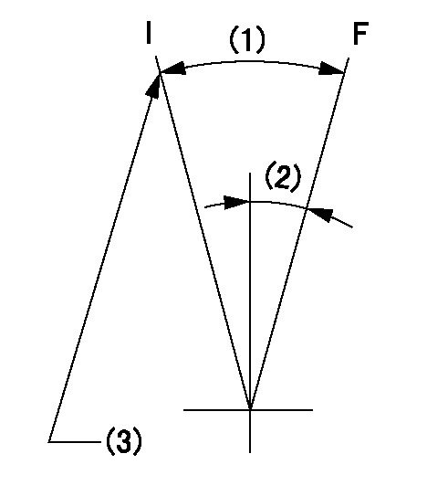
F:Full speed
I:Idle
(1)Actual measurement
(2)Actual measurement
(3)Stopper bolt setting
----------
----------
----------
----------
Stop lever angle

N:Pump normal
S:Stop the pump.
----------
----------
a=35deg+-5deg b=45deg+-5deg
----------
----------
a=35deg+-5deg b=45deg+-5deg
Timing setting

(1)Pump vertical direction
(2)Position of middle of pump side coupling's elongated hole at No 1 cylinder's beginning of injection
(3)-
(4)-
----------
----------
a=(50deg)
----------
----------
a=(50deg)
Information:
Accidental engine starting can cause injury or death to personnel working on the equipment.To avoid accidental engine starting, disconnect the battery cable from the negative (−) battery terminal. Completely tape all metal surfaces of the disconnected battery cable end in order to prevent contact with other metal surfaces which could activate the engine electrical system.Place a Do Not Operate tag at the Start/Stop switch location to inform personnel that the equipment is being worked on.
Water Temperature Fault (WT)
The current flow for the circuit that is described in this section is applicable for all engines. The engine must be running at a speed with a coolant temperature that is hot enough to close the water temperature contactor switch (WTS). The water temperature contactor switch is normally open. The following events occur in the electric circuit in order to shut down the engine. The engine will shut down when the temperature of the coolant system is greater than the maximum temperature that is set for the WTS.
The water temperature contactor switch (WTS) closes across the contacts , which are normally open.
Closing the contacts (WTS-1) and (WTS-2) opens the circuit to slave relay (SR1) (line 33).
When the open circuit de-energizes (SR1) and (SR2), the circuit opens across the relay contacts (SR1-30) and (SR1-87) (line 43).
The open circuit de-energizes the fuel solenoid (FS) which shuts off the fuel flow to the engine. The starter motor circuit can then be engaged. However, there is no fuel flow to the engine and the engine cannot be restarted until the coolant temperature falls below the rating of the water temperature contactor switch. When the water temperature is below the maximum rating for the temperature of the WTS, the circuit opens across contacts (WTS-1) and (WTS-2). The slave relay (SR1) and the fuel solenoid (FS) can then be energized by the engine starting circuit in order to restart the engine.
To avoid possible engine damage or another immediate shutdown, the water temperature fault must be corrected before attempting to restart the engine.
Accidental engine starting can cause injury or death to personnel working on the equipment.To avoid accidental engine starting, disconnect the battery cable from the negative (−) battery terminal. Completely tape all metal surfaces of the disconnected battery cable end in order to prevent contact with other metal surfaces which could activate the engine electrical system.Place a Do Not Operate tag at the Start/Stop switch location to inform personnel that the equipment is being worked on.
2301A Electric Governor Control
The 2301A Electric Governor Control activates all of the components that are in the electric protection system. The components are activated in the same manner when the nonelectric governor is used. One difference exists in the main circuit. The fuel shutoff solenoid (FSOS) (line 43) is not used.When the electric governor control is used, the engine must run in a normal condition in order for the electric circuit to operate in the manner that is described below.
Current flows from the terminals (TS-28) (line 30) and (TS-31) (line 31), which