Information injection-pump assembly
ZEXEL
103682-0430
1036820430
KOMATSU
6162731681
6162731681

Rating:
Service parts 103682-0430 INJECTION-PUMP ASSEMBLY:
1.
_
7.
COUPLING PLATE
8.
_
9.
_
11.
Nozzle and Holder
12.
Open Pre:MPa(Kqf/cm2)
29.4(300)
15.
NOZZLE SET
Cross reference number
ZEXEL
103682-0430
1036820430
KOMATSU
6162731681
6162731681
Zexel num
Bosch num
Firm num
Name
Calibration Data:
Adjustment conditions
Test oil
1404 Test oil ISO4113 or {SAEJ967d}
1404 Test oil ISO4113 or {SAEJ967d}
Test oil temperature
degC
40
40
45
Nozzle and nozzle holder
105780-8130
Bosch type code
EFEP215A
Nozzle
105780-0050
Bosch type code
DN6TD119NP1T
Nozzle holder
105780-2090
Bosch type code
EFEP215
Opening pressure
MPa
17.2
Opening pressure
kgf/cm2
175
Injection pipe
Outer diameter - inner diameter - length (mm) mm 8-4-1500
Outer diameter - inner diameter - length (mm) mm 8-4-1500
Overflow valve (drive side)
131425-1620
Overflow valve opening pressure (drive side)
kPa
255
221
289
Overflow valve opening pressure (drive side)
kgf/cm2
2.6
2.25
2.95
Overflow valve (governor side)
131425-1620
Overflow valve opening pressure (governor side)
kPa
255
221
289
Overflow valve opening pressure (governor side)
kgf/cm2
2.6
2.25
2.95
Tester oil delivery pressure
kPa
157
157
157
Tester oil delivery pressure
kgf/cm2
1.6
1.6
1.6
Direction of rotation (viewed from drive side)
Left L
Left L
Injection timing adjustment
Direction of rotation (viewed from drive side)
Left L
Left L
Injection order
1-5-3-6-
2-4
Pre-stroke
mm
4.5
4.45
4.55
Beginning of injection position
Drive side NO.1
Drive side NO.1
Difference between angles 1
Cal 1-5 deg. 60 59.5 60.5
Cal 1-5 deg. 60 59.5 60.5
Difference between angles 2
Cal 1-3 deg. 120 119.5 120.5
Cal 1-3 deg. 120 119.5 120.5
Difference between angles 3
Cal 1-6 deg. 180 179.5 180.5
Cal 1-6 deg. 180 179.5 180.5
Difference between angles 4
Cyl.1-2 deg. 240 239.5 240.5
Cyl.1-2 deg. 240 239.5 240.5
Difference between angles 5
Cal 1-4 deg. 300 299.5 300.5
Cal 1-4 deg. 300 299.5 300.5
Injection quantity adjustment
Adjusting point
A
Rack position
16.5
Pump speed
r/min
1000
1000
1000
Average injection quantity
mm3/st.
589
584
594
Max. variation between cylinders
%
0
-4
4
Basic
*
Fixing the lever
*
Injection quantity adjustment_02
Adjusting point
B
Rack position
8.1+-0.5
Pump speed
r/min
300
300
300
Average injection quantity
mm3/st.
58
53
63
Max. variation between cylinders
%
0
-14
14
Fixing the rack
*
Injection quantity adjustment_03
Adjusting point
D
Rack position
17+0.2
Pump speed
r/min
100
100
100
Average injection quantity
mm3/st.
450
450
490
Fixing the lever
*
Rack limit
*
Test data Ex:
Governor adjustment
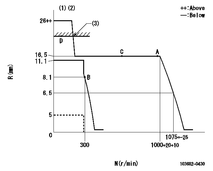
N:Pump speed
R:Rack position (mm)
(1)Target notch: K
(2)Deliver without the torque control spring operating.
(3)RACK LIMIT: RAL
----------
K=5 RAL=17+0.2mm
----------
----------
K=5 RAL=17+0.2mm
----------
Speed control lever angle
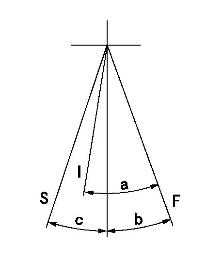
F:Full speed
I:Idle
S:Stop
----------
----------
a=(33deg)+-5deg b=(13deg)+-5deg c=30deg+-3deg
----------
----------
a=(33deg)+-5deg b=(13deg)+-5deg c=30deg+-3deg
Stop lever angle
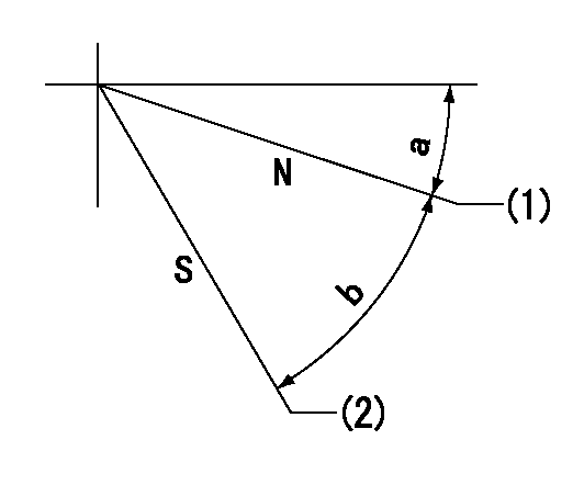
N:Pump normal
S:Stop the pump.
(1)Clearance between stopper bolt and lever must be aa.
(2)At pump speed bb and rack position cc, set the stopper bolt.
----------
aa=(0.8)mm bb=100r/min cc=5mm
----------
a=24deg+-5deg b=40deg+-5deg
----------
aa=(0.8)mm bb=100r/min cc=5mm
----------
a=24deg+-5deg b=40deg+-5deg
0000001501 Q ADJUSTMENT PIPING
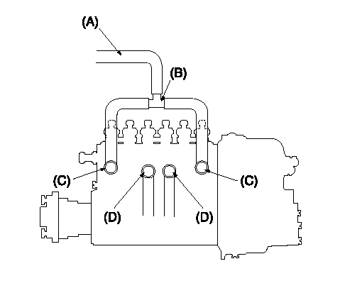
Tester fuel pipe A
(B) branch piping
Fuel inlet C
(D) Overflow valve
Piping at standard injection quantity adjustment
1. Because the pump gallery is divided into two, be careful of the fuel piping at adjustment.
----------
----------
----------
----------
Timing setting

(1)Pump vertical direction
(2)Coupling's key groove position at No 1 cylinder's beginning of injection
(3)-
(4)-
----------
----------
a=(70deg)
----------
----------
a=(70deg)
Information:
Illustration 1 g00564355
7W-2743 Electronic Speed Switch (ESS)
(1) Push button for Overspeed Verification
(2) Reset button
(3) Overspeed indicator lamp
(4) Seal screw plug for adjusting the engine overspeed
(5) Seal screw plug for adjusting the crank terminate speed
(6) Seal screw plug for adjusting the oil step pressure speed setting The overspeed calibration can increase the overspeed setting or the overspeed calibration can decrease the overspeed setting in order to shut down the engine when the overspeed verification button is pressed. The overspeed setting is correctly made when the engine is running at 75% of the overspeed setting. The engine then shuts down when the overspeed verification button is pressed.Use the following procedure in order to adjust the overspeed setting.
Remove the lockwire and the seal from seal screw plug (4). Remove seal screw plug (4) from the access hole for the overspeed adjustment screw.
Use a small screwdriver to lightly turn the overspeed adjustment screw in the direction of the "MAX" arrow or the clockwise direction. Turn the screw 20 times. The overspeed adjustment screw will vary the setting of a potentiometer that is inside of the ESS. The overspeed adjustment screw will not cause damage to the potentiometer. Also, the screw can not be removed if the screw is turned in the wrong direction.
Run the engine at 75% of the desired overspeed setting rpm. Refer to the Speed Specification Chart.
While the engine is running at 75% of the overspeed setting rpm, press "VERIFY" button (1). While the button is depressed, slowly turn the overspeed adjustment screw in the opposite direction of the "MAX" arrow or the counterclockwise direction until overspeed indicator lamp (3) is lighted. The engine will shut down if the ESS is connected to the fuel shutoff solenoid (FSOS) and the air shutoff solenoid, if equipped.
In order to reset the ESS, press "RESET" button (2). The air shutoff valve must be reset by hand, if equipped.
Slowly turn the overspeed adjustment screw in the clockwise direction for one turn. Repeat Steps 3, 4, and 5. More adjustment may be necessary in order to gain the correct setting. Turn the overspeed adjustment screw in the clockwise direction in order to increase the overspeed setting. Turn the overspeed adjustment screw in the counterclockwise direction in order to decrease the overspeed setting.
When the overspeed setting is correct, install seal screw plug (4) in the access hole for the overspeed adjustment screw. Tighten the screw to a torque of 0.20 0.03 N m (1.8 .3 lb in). Install the lockwire and the seal if the calibration of the crank termination speed and the oil step speed calibration are also complete.