Information injection-pump assembly
BOSCH
9 400 616 362
9400616362
ZEXEL
103682-0420
1036820420
KOMATSU
6162731652
6162731652
Rating:
Service parts 103682-0420 INJECTION-PUMP ASSEMBLY:
1.
_
5.
AUTOM. ADVANCE MECHANIS
7.
COUPLING PLATE
8.
_
9.
_
11.
Nozzle and Holder
6164-11-3101
12.
Open Pre:MPa(Kqf/cm2)
29.4{300}
15.
NOZZLE SET
Cross reference number
BOSCH
9 400 616 362
9400616362
ZEXEL
103682-0420
1036820420
KOMATSU
6162731652
6162731652
Zexel num
Bosch num
Firm num
Name
Calibration Data:
Adjustment conditions
Test oil
1404 Test oil ISO4113 or {SAEJ967d}
1404 Test oil ISO4113 or {SAEJ967d}
Test oil temperature
degC
40
40
45
Nozzle and nozzle holder
105780-8130
Bosch type code
EFEP215A
Nozzle
105780-0050
Bosch type code
DN6TD119NP1T
Nozzle holder
105780-2090
Bosch type code
EFEP215
Opening pressure
MPa
17.2
Opening pressure
kgf/cm2
175
Injection pipe
Outer diameter - inner diameter - length (mm) mm 8-4-1500
Outer diameter - inner diameter - length (mm) mm 8-4-1500
Overflow valve (drive side)
131425-1620
Overflow valve opening pressure (drive side)
kPa
255
221
289
Overflow valve opening pressure (drive side)
kgf/cm2
2.6
2.25
2.95
Overflow valve (governor side)
131425-1620
Overflow valve opening pressure (governor side)
kPa
255
221
289
Overflow valve opening pressure (governor side)
kgf/cm2
2.6
2.25
2.95
Tester oil delivery pressure
kPa
157
157
157
Tester oil delivery pressure
kgf/cm2
1.6
1.6
1.6
Direction of rotation (viewed from drive side)
Left L
Left L
Injection timing adjustment
Direction of rotation (viewed from drive side)
Left L
Left L
Injection order
1-5-3-6-
2-4
Pre-stroke
mm
4.5
4.45
4.55
Beginning of injection position
Drive side NO.1
Drive side NO.1
Difference between angles 1
Cal 1-5 deg. 60 59.5 60.5
Cal 1-5 deg. 60 59.5 60.5
Difference between angles 2
Cal 1-3 deg. 120 119.5 120.5
Cal 1-3 deg. 120 119.5 120.5
Difference between angles 3
Cal 1-6 deg. 180 179.5 180.5
Cal 1-6 deg. 180 179.5 180.5
Difference between angles 4
Cyl.1-2 deg. 240 239.5 240.5
Cyl.1-2 deg. 240 239.5 240.5
Difference between angles 5
Cal 1-4 deg. 300 299.5 300.5
Cal 1-4 deg. 300 299.5 300.5
Injection quantity adjustment
Adjusting point
A
Rack position
15.5
Pump speed
r/min
1000
1000
1000
Average injection quantity
mm3/st.
535
530
540
Max. variation between cylinders
%
0
-4
4
Basic
*
Fixing the lever
*
Injection quantity adjustment_02
Adjusting point
B
Rack position
8.1+-0.5
Pump speed
r/min
300
300
300
Average injection quantity
mm3/st.
58
53
63
Max. variation between cylinders
%
0
-14
14
Fixing the rack
*
Injection quantity adjustment_03
Adjusting point
C
Rack position
16+0.2
Pump speed
r/min
100
100
100
Average injection quantity
mm3/st.
390
390
430
Fixing the lever
*
Rack limit
*
Test data Ex:
Governor adjustment
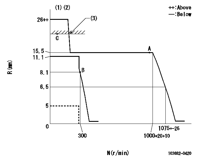
N:Pump speed
R:Rack position (mm)
(1)Target notch: K
(2)Deliver without the torque control spring operating.
(3)RACK LIMIT: RAL
----------
K=9 RAL=16+0.2mm
----------
----------
K=9 RAL=16+0.2mm
----------
Speed control lever angle
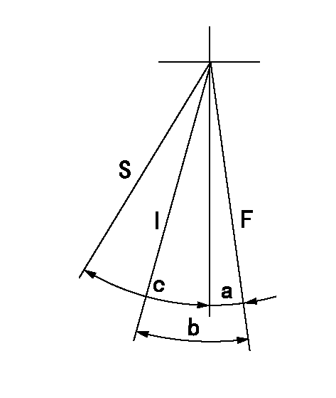
F:Full speed
I:Idle
S:Stop
----------
----------
a=(16deg)+-5deg b=(42deg)+-5deg c=30deg+-3deg
----------
----------
a=(16deg)+-5deg b=(42deg)+-5deg c=30deg+-3deg
Stop lever angle
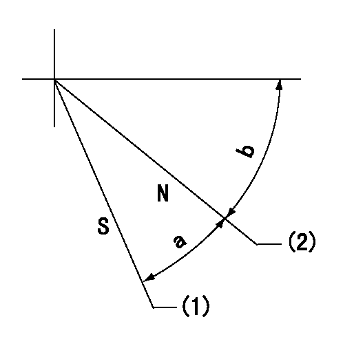
N:Pump normal
S:Stop the pump.
(1)Set the stopper bolt at speed = aa and rack position = bb.
(2)Clearance between stopper bolt and lever must be cc.
----------
aa=100r/min bb=5mm cc=(0.8)mm
----------
a=40deg+-5deg b=24deg+-5deg
----------
aa=100r/min bb=5mm cc=(0.8)mm
----------
a=40deg+-5deg b=24deg+-5deg
0000001501 Q ADJUSTMENT PIPING
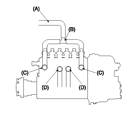
Tester fuel pipe A
(B) branch piping
Fuel inlet C
(D) Overflow valve
Piping at standard injection quantity adjustment
1. Because the pump gallery is divided into two, be careful of the fuel piping at adjustment.
----------
----------
----------
----------
Timing setting

(1)Pump vertical direction
(2)Coupling's key groove position at No 1 cylinder's beginning of injection
(3)-
(4)-
----------
----------
a=(70deg)
----------
----------
a=(70deg)
Information:
Test 1 - Overspeed Switch (OS)
Table 1
Overspeed Switch (OS)
Step Engine RPM Action Correct Result
A 25 + 5 rpm less than 75% Overspeed Verify rpm Press the 75% Verify button No engine shutdown
B 25 + 5 rpm more than 75% Overspeed Verify rpm Press the 75% Verify button Air and fuel shutoff
C Manually reset the air shutoff lever at the top of the air inlet, if equipped. Press the ESS reset button. Test 2 - Emergency Stop Switch (ES)
Table 2
Emergency Stop Switch (ES)
Step Engine RPM Action Correct Result
A Any rpm above the crank terminate rpm Press the push button for the emergency stop switch Air and fuel shutoff
B Manually reset the air shutoff lever at the top of the air inlet, if equipped. Turn ES switch in the dirction that is shown on the face of the push button in order to reset the switch. Test 3 - Normal Stop Switch (NSS)
Table 3
Normal Stop Switch (NSS)
Step Engine RPM Action Correct Result
A Any rpm above the crank terminate rpm Push the normal stop switch (NSS) Fuel shutoff Test 4 - Water Temperature Contactor Switch
Table 4
Water Temperature Contactor Switch (WTS)
Step Engine RPM Action Correct Result
A Any rpm above the crank terminate rpm Place a jumper across terminals TS-2 and TS-7. Fuel shutoff
B Remove the jumper from terminals TS-2 and TS-7. Test 5 - Oil Pressure Switch (OPS1)
Table 5
Oil Pressure Switch (OPS1)
Step Engine RPM Action Correct Result
A Any rpm above the crank terminate rpm Place a jumper across terminals OPS1-1 and OPS1-3. Fuel shutoff
B Remove the jumper from terminals OPS1-1 and OPS1-3. Test 6 - Oil Pressure Switch (OPS2)
Table 6
Oil Pressure Switch (OPS2)
Step Engine RPM Action Correct Result
A 25 + 5 rpm less than the setting for the oil step speed Place a jumper across terminals OPS2-1 and OPS2-3. No engine shutdown.
B 25 + 5 rpm more than the setting for the oil step speed Place a jumper across terminals OPS2-1 and OPS2-3. Fuel shutoff 9 seconds after the oil step speed is reached.
C Remove the jumper from across terminals OPS2-1 and OPS2-3.