Information injection-pump assembly
ZEXEL
103682-0360
1036820360
NIIGATA-URAWA
4044714OA
4044714oa

Rating:
Service parts 103682-0360 INJECTION-PUMP ASSEMBLY:
1.
_
5.
AUTOM. ADVANCE MECHANIS
6.
COUPLING PLATE
7.
COUPLING PLATE
8.
_
9.
_
11.
Nozzle and Holder
503 3225 0A
12.
Open Pre:MPa(Kqf/cm2)
12.7{130}
15.
NOZZLE SET
Cross reference number
ZEXEL
103682-0360
1036820360
NIIGATA-URAWA
4044714OA
4044714oa
Zexel num
Bosch num
Firm num
Name
103682-0360
4044714OA NIIGATA-URAWA
INJECTION-PUMP ASSEMBLY
6L18 * K
6L18 * K
Calibration Data:
Adjustment conditions
Test oil
1404 Test oil ISO4113 or {SAEJ967d}
1404 Test oil ISO4113 or {SAEJ967d}
Test oil temperature
degC
40
40
45
Nozzle
105000-1040
Bosch type code
DN0SD130
Nozzle holder
105031-3010
Bosch type code
KB75SDN18
Opening pressure
MPa
12.7
Opening pressure
kgf/cm2
130
Injection pipe
Outer diameter - inner diameter - length (mm) mm 8-3-540
Outer diameter - inner diameter - length (mm) mm 8-3-540
Overflow valve
132424-0620
Overflow valve opening pressure
kPa
157
123
191
Overflow valve opening pressure
kgf/cm2
1.6
1.25
1.95
Tester oil delivery pressure
kPa
157
157
157
Tester oil delivery pressure
kgf/cm2
1.6
1.6
1.6
Direction of rotation (viewed from drive side)
Right R
Right R
Injection timing adjustment
Direction of rotation (viewed from drive side)
Right R
Right R
Injection order
1-4-2-6-
3-5
Pre-stroke
mm
2.05
2
2.1
Beginning of injection position
Drive side NO.1
Drive side NO.1
Difference between angles 1
Cal 1-4 deg. 60 59.5 60.5
Cal 1-4 deg. 60 59.5 60.5
Difference between angles 2
Cyl.1-2 deg. 120 119.5 120.5
Cyl.1-2 deg. 120 119.5 120.5
Difference between angles 3
Cal 1-6 deg. 180 179.5 180.5
Cal 1-6 deg. 180 179.5 180.5
Difference between angles 4
Cal 1-3 deg. 240 239.5 240.5
Cal 1-3 deg. 240 239.5 240.5
Difference between angles 5
Cal 1-5 deg. 300 299.5 300.5
Cal 1-5 deg. 300 299.5 300.5
Injection quantity adjustment
Adjusting point
A
Rack position
16
Pump speed
r/min
750
750
750
Average injection quantity
mm3/st.
660
630
690
Max. variation between cylinders
%
0
-3
3
Basic
*
Fixing the rack
*
Injection quantity adjustment_02
Adjusting point
C
Rack position
9.6+-0.5
Pump speed
r/min
230
230
230
Average injection quantity
mm3/st.
81
73
89
Max. variation between cylinders
%
0
-10
10
Fixing the rack
*
Test data Ex:
Governor adjustment
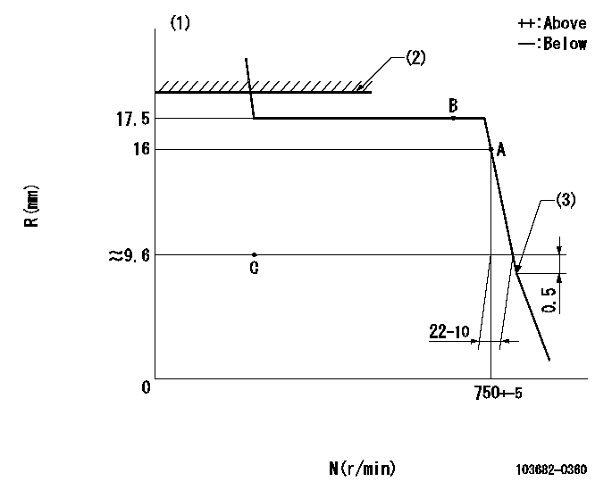
N:Pump speed
R:Rack position (mm)
(1)Target notch: K
(2)RACK LIMIT: RAL
(3)Beginning of sub spring operation
----------
K=20 RAL=18.5+0.5mm
----------
----------
K=20 RAL=18.5+0.5mm
----------
Speed control lever angle
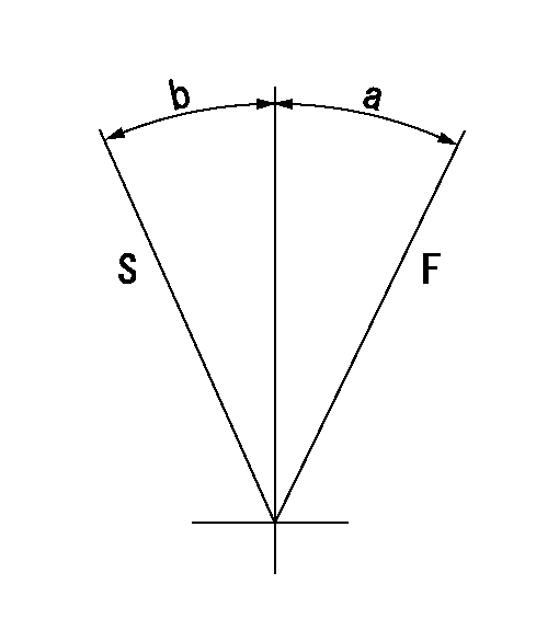
F:Full speed
S:Stop
----------
----------
a=(34deg) b=(27deg)
----------
----------
a=(34deg) b=(27deg)
Information:
Never use water alone as a coolant. Water alone is corrosive at engine operating temperatures. In addition, water alone does not provide adequate protection against boiling or freezing.
In engine cooling systems that use water alone, Caterpillar recommends the use of Cat SCA. Cat SCA helps to prevent the following conditions from occurring:
Corrosion
Formation of mineral deposits
Cavitation erosion of the cylinder liner
Foaming of the coolantIf Cat SCA is not used, select a fully formulated commercial SCA. The commercial SCA must provide a minimum of 2400 mg/L or 2400 ppm (140 grains/US gal) of nitrites in the final coolant mixture.The quality of the water is an important factor in this type of cooling system. Distilled water or deionized water is recommended for use in cooling systems. If distilled water or deionized water is not available, use water that meets or exceeds the minimum requirements that are listed in the table for recommended water properties in this Special Publication, "General Coolant Information" topic.A cooling system that uses a mixture of SCA and water only needs more SCA. The SCA concentration in a cooling system that uses SCA and water should be 6 to 8 percent by volume.Maintain the Cat SCA in the same way as you would maintain a cooling system that uses heavy-duty coolant/antifreeze. Adjust the maintenance for the amount ofCat SCA additions.Adding the Cat SCA to Water at the Initial Fill
Use the equation that is in this Special Publication, "Conventional Coolant/Antifreeze Cooling System Maintenance" to determine the amount of Cat SCA that is required at the initial fill. This equation is for a mixture of only Cat SCA and water.Adding the Cat SCA to Water for Maintenance
For the recommended service interval, refer to the Operation and Maintenance Manual, "Maintenance Interval Schedule" for your engine.Submit a coolant sample to your Cat dealer. See this Special Publication, "S O S Services Coolant Analysis" topic.Additions of Cat SCA are based on the results of the coolant analysis. The size of the cooling system determines the amount of Cat SCA that is required.Use the equation that is in this Special Publication, "Conventional Coolant/Antifreeze Cooling System Maintenance" to determine the amount of Cat SCA that is required for maintenance, if necessary:Note: Specific engine applications may require maintenance practices to be periodically evaluated in order to maintain properly the engine cooling system.SCA and part numbers are available from your Cat dealer.
Have questions with 103682-0360?
Group cross 103682-0360 ZEXEL
Shinko-Engin.
Fuji-Diesel
Niigata-Urawa
103682-0360
4044714OA
INJECTION-PUMP ASSEMBLY
6L18
6L18