Information injection-pump assembly
BOSCH
9 400 611 949
9400611949
ZEXEL
103662-3360
1036623360
Rating:
Service parts 103662-3360 INJECTION-PUMP ASSEMBLY:
1.
_
7.
COUPLING PLATE
8.
_
9.
_
11.
Nozzle and Holder
6162-13-8902
12.
Open Pre:MPa(Kqf/cm2)
29.4{300}
15.
NOZZLE SET
Cross reference number
BOSCH
9 400 611 949
9400611949
ZEXEL
103662-3360
1036623360
Zexel num
Bosch num
Firm num
Name
Calibration Data:
Adjustment conditions
Test oil
1404 Test oil ISO4113 or {SAEJ967d}
1404 Test oil ISO4113 or {SAEJ967d}
Test oil temperature
degC
40
40
45
Nozzle and nozzle holder
105780-8130
Bosch type code
EFEP215A
Nozzle
105780-0050
Bosch type code
DN6TD119NP1T
Nozzle holder
105780-2090
Bosch type code
EFEP215
Opening pressure
MPa
17.2
Opening pressure
kgf/cm2
175
Injection pipe
Outer diameter - inner diameter - length (mm) mm 8-4-1500
Outer diameter - inner diameter - length (mm) mm 8-4-1500
Overflow valve
131425-2020
Overflow valve opening pressure
kPa
255
221
289
Overflow valve opening pressure
kgf/cm2
2.6
2.25
2.95
Tester oil delivery pressure
kPa
157
157
157
Tester oil delivery pressure
kgf/cm2
1.6
1.6
1.6
Direction of rotation (viewed from drive side)
Left L
Left L
Injection timing adjustment
Direction of rotation (viewed from drive side)
Left L
Left L
Injection order
1-5-3-6-
2-4
Pre-stroke
mm
3.8
3.75
3.85
Beginning of injection position
Drive side NO.1
Drive side NO.1
Difference between angles 1
Cal 1-5 deg. 60 59.5 60.5
Cal 1-5 deg. 60 59.5 60.5
Difference between angles 2
Cal 1-3 deg. 120 119.5 120.5
Cal 1-3 deg. 120 119.5 120.5
Difference between angles 3
Cal 1-6 deg. 180 179.5 180.5
Cal 1-6 deg. 180 179.5 180.5
Difference between angles 4
Cyl.1-2 deg. 240 239.5 240.5
Cyl.1-2 deg. 240 239.5 240.5
Difference between angles 5
Cal 1-4 deg. 300 299.5 300.5
Cal 1-4 deg. 300 299.5 300.5
Injection quantity adjustment
Adjusting point
A
Rack position
18.3
Pump speed
r/min
1050
1050
1050
Average injection quantity
mm3/st.
499
494
504
Max. variation between cylinders
%
0
-4
4
Basic
*
Fixing the lever
*
Boost pressure
kPa
92
92
Boost pressure
mmHg
690
690
Injection quantity adjustment_02
Adjusting point
B
Rack position
10.5+-0.
5
Pump speed
r/min
300
300
300
Average injection quantity
mm3/st.
44.5
39.5
49.5
Max. variation between cylinders
%
0
-14
14
Fixing the rack
*
Boost pressure
kPa
0
0
0
Boost pressure
mmHg
0
0
0
Injection quantity adjustment_03
Adjusting point
C
Rack position
-
Pump speed
r/min
100
100
100
Average injection quantity
mm3/st.
485
485
505
Fixing the lever
*
Boost pressure
kPa
0
0
0
Boost pressure
mmHg
0
0
0
Rack limit
*
Boost compensator adjustment
Pump speed
r/min
650
650
650
Rack position
R1-4.4
Boost pressure
kPa
16
13.3
18.7
Boost pressure
mmHg
120
100
140
Boost compensator adjustment_02
Pump speed
r/min
650
650
650
Rack position
R1(18.3)
Boost pressure
kPa
78.6
71.9
85.3
Boost pressure
mmHg
590
540
640
Test data Ex:
Governor adjustment
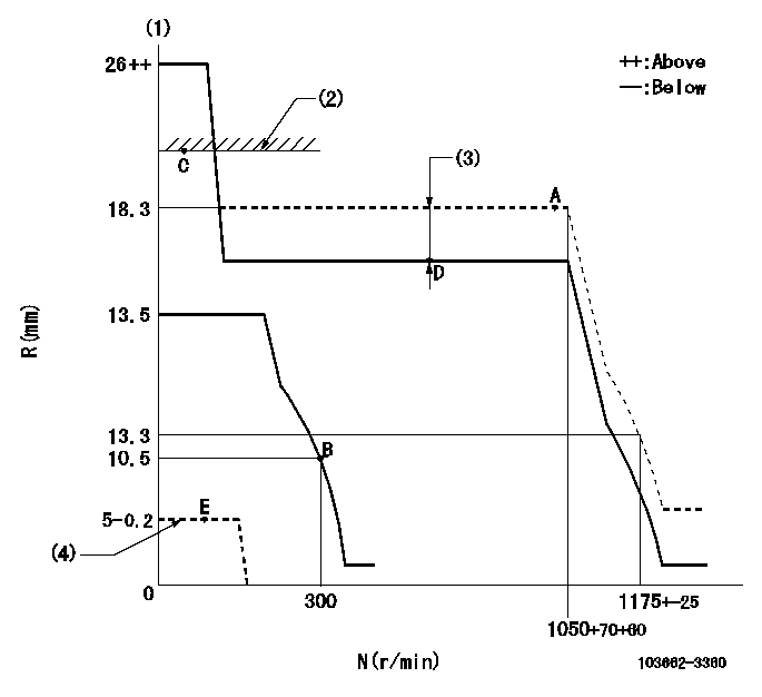
N:Pump speed
R:Rack position (mm)
(1)Target notch: K
(2)RACK LIMIT
(3)Boost compensator stroke: BCL
(4)Stop lever at stopping (with the speed lever at full, 0 boost)
----------
K=19 BCL=4.4+-0.1mm
----------
----------
K=19 BCL=4.4+-0.1mm
----------
Speed control lever angle
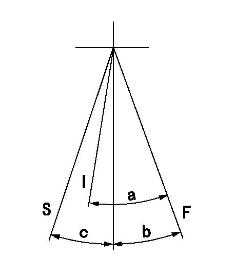
F:Full speed
I:Idle
S:Stop
----------
----------
a=37deg+-5deg b=28deg+-5deg c=30deg+-3deg
----------
----------
a=37deg+-5deg b=28deg+-5deg c=30deg+-3deg
Stop lever angle
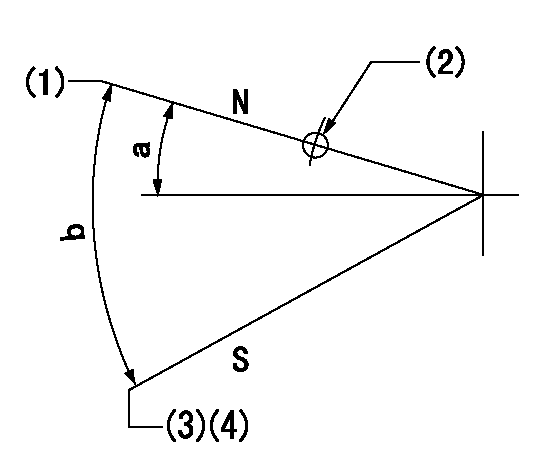
N:Pump normal
S:Stop the pump.
(1)The clearance from the set screw must be aa.
(2)Use the hole at R = bb
(3)Set the screw so that speed = cc, rack position = dd
(4)At speed lever full, 0 boost
----------
aa=2+1mm bb=40mm cc=100r/min dd=5-0.2mm
----------
a=16deg+-5deg b=40deg+-5deg
----------
aa=2+1mm bb=40mm cc=100r/min dd=5-0.2mm
----------
a=16deg+-5deg b=40deg+-5deg
Timing setting

(1)Pump vertical direction
(2)Coupling's key groove position at No 1 cylinder's beginning of injection
(3)-
(4)-
----------
----------
a=(70deg)
----------
----------
a=(70deg)
Information:
1. Disconnect boost hose (2) at fuel ratio control (1).2. Remove lockwire (3) and the seal from the bolts.3. Remove the two bolts that hold fuel ratio control (1).4. Pull up on the fuel ratio control, and move it toward the front of the engine so the valve on the fuel ratio will disengage with the groove (slot) in the governor collar. Remove the fuel ratio control and gasket. The following steps are for installation of the fuel ratio control.5. Install a new gasket on fuel ratio control (1).6. Engage valve (4) with the groove (slot) in collar (5) for the governor.7. Install the bolts that hold fuel ratio control (1) to the governor plate.8. Connect boost hose (2) to the fuel ratio control.9. Install new lockwire (3) and seal. See Fuel Rack Setting in Testing And Adjusting.10. Lower the hoods.Disassemble Fuel Ratio Control
Start By:a. remove fuel ratio control The illustrations which follow show a different design fuel ratio control. However, the service procedure is the same. 1. Remove two bolts (1) and cover (2). 2. Remove valve assembly (3).3. Remove seal (4) and the O-ring seal from the valve assembly.4. Remove retainer (5) and two springs (6). 5. Remove the three bolts from the cover. Remove cover (12) and gasket (11).6. Remove valve (13), diaphragm (8), retainer (9) and spring (10).7. Remove pin (14) from valve (13).8. Remove cover (7) from the valve.Assemble Fuel Ratio Control
The illustrations which follow show a different design fuel ratio control. However, the service procedure is the same. 1. Put clean SAE 30 Oil on the seal. Install seal (1) in cover (2) with the lip of the seal toward the inside of the cover. 2. Install valve (3) in cover (2).3. Install the pin that holds the cover on the valve. 4. Install the spring and the retainer in cover (6).5. Install diaphragm (5) on valve assembly (4) and in the cover.6. Install cover (8). Install three bolts (7) that hold the cover in position. 7. Put clean SAE 30 Oil on the seal and the ring seal. Install seals (11) on the valve.8. Install two springs (12), retainer (13) and valve assembly (10).9. Install housing (9) and the bolts.
Correct adjustment must be made to fuel ratio control before installation. See the topic "Adjustment Of Air Fuel Ratio Control" in Testing & Adjusting.
End By:a. install fuel ratio control