Information injection-pump assembly
ZEXEL
103662-3100
1036623100
KOMATSU
6162731570
6162731570

Rating:
Service parts 103662-3100 INJECTION-PUMP ASSEMBLY:
1.
_
5.
AUTOM. ADVANCE MECHANIS
7.
COUPLING PLATE
8.
_
9.
_
11.
Nozzle and Holder
6162-13-3902
12.
Open Pre:MPa(Kqf/cm2)
29.4{300}
15.
NOZZLE SET
Cross reference number
ZEXEL
103662-3100
1036623100
KOMATSU
6162731570
6162731570
Zexel num
Bosch num
Firm num
Name
Calibration Data:
Adjustment conditions
Test oil
1404 Test oil ISO4113 or {SAEJ967d}
1404 Test oil ISO4113 or {SAEJ967d}
Test oil temperature
degC
40
40
45
Nozzle and nozzle holder
105780-8130
Bosch type code
EFEP215A
Nozzle
105780-0050
Bosch type code
DN6TD119NP1T
Nozzle holder
105780-2090
Bosch type code
EFEP215
Opening pressure
MPa
17.2
Opening pressure
kgf/cm2
175
Injection pipe
Outer diameter - inner diameter - length (mm) mm 8-4-1500
Outer diameter - inner diameter - length (mm) mm 8-4-1500
Overflow valve
133424-0420
Overflow valve opening pressure
kPa
206
172
240
Overflow valve opening pressure
kgf/cm2
2.1
1.75
2.45
Tester oil delivery pressure
kPa
157
157
157
Tester oil delivery pressure
kgf/cm2
1.6
1.6
1.6
Direction of rotation (viewed from drive side)
Left L
Left L
Injection timing adjustment
Direction of rotation (viewed from drive side)
Left L
Left L
Injection order
1-5-3-6-
2-4
Pre-stroke
mm
3.8
3.75
3.85
Beginning of injection position
Drive side NO.1
Drive side NO.1
Difference between angles 1
Cal 1-5 deg. 60 59.5 60.5
Cal 1-5 deg. 60 59.5 60.5
Difference between angles 2
Cal 1-3 deg. 120 119.5 120.5
Cal 1-3 deg. 120 119.5 120.5
Difference between angles 3
Cal 1-6 deg. 180 179.5 180.5
Cal 1-6 deg. 180 179.5 180.5
Difference between angles 4
Cyl.1-2 deg. 240 239.5 240.5
Cyl.1-2 deg. 240 239.5 240.5
Difference between angles 5
Cal 1-4 deg. 300 299.5 300.5
Cal 1-4 deg. 300 299.5 300.5
Injection quantity adjustment
Adjusting point
A
Rack position
16.6
Pump speed
r/min
1000
1000
1000
Average injection quantity
mm3/st.
473.5
468.5
478.5
Max. variation between cylinders
%
0
-4
4
Basic
*
Fixing the lever
*
Boost pressure
kPa
50.7
50.7
Boost pressure
mmHg
380
380
Injection quantity adjustment_02
Adjusting point
B
Rack position
9.1+-0.5
Pump speed
r/min
350
350
350
Average injection quantity
mm3/st.
48
44
52
Max. variation between cylinders
%
0
-14
14
Fixing the rack
*
Boost pressure
kPa
0
0
0
Boost pressure
mmHg
0
0
0
Injection quantity adjustment_03
Adjusting point
C
Rack position
18
Pump speed
r/min
700
700
700
Average injection quantity
mm3/st.
488
483
493
Fixing the lever
*
Boost pressure
kPa
50.7
50.7
Boost pressure
mmHg
380
380
Boost compensator adjustment
Pump speed
r/min
500
500
500
Rack position
14
Boost pressure
kPa
12
12
12
Boost pressure
mmHg
90
90
90
Boost compensator adjustment_02
Pump speed
r/min
500
500
500
Rack position
18
Boost pressure
kPa
41.3
38.6
44
Boost pressure
mmHg
310
290
330
Test data Ex:
Governor adjustment
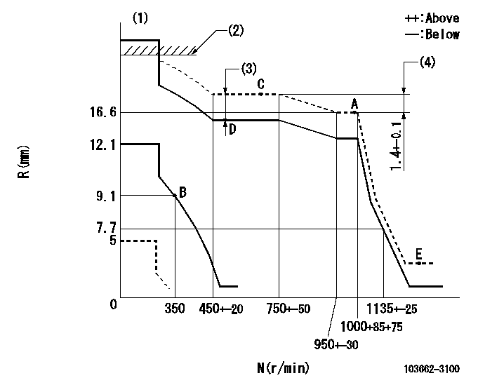
N:Pump speed
R:Rack position (mm)
(1)Notch: K
(2)RACK LIMIT: RAL
(3)Boost compensator stroke: BCL
(4)Rack difference between N = N1 and N = N2
----------
K=10 RAL=20+0.2mm BCL=4+-0.1mm N1=1000r/min N2=700r/min
----------
----------
K=10 RAL=20+0.2mm BCL=4+-0.1mm N1=1000r/min N2=700r/min
----------
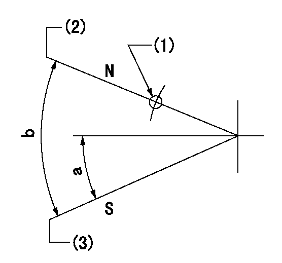
Speed control lever angle

F:Full speed
I:Idle
(1)Stopper bolt setting
----------
----------
a=17deg+-5deg b=38deg+-5deg
----------
----------
a=17deg+-5deg b=38deg+-5deg
Stop lever angle
N:Pump normal
S:Stop the pump.
(1)Use the pin at R = aa
(2)The clearance from the set screw must be bb.
(3)Set the screw at speed = cc and rack position = dd.
----------
aa=44mm bb=2+1mm cc=100r/min dd=5mm
----------
a=20deg+-5deg b=40deg+-5deg
----------
aa=44mm bb=2+1mm cc=100r/min dd=5mm
----------
a=20deg+-5deg b=40deg+-5deg
Information:
Start By:a. remove valve covers 1. Use Tool (A) to disconnect fuel injection line (1) at both ends. Remove the fuel injection line from the engine. 2. Use Tool (B) to remove retainer (2) from the adapter.3. Remove the fuel injection nozzles with Tooling (C) as follows:a. Install the 6V-6983 Adapter and the 8T-3199 Screw into nozzle assembly (3).b. Install the 8T-3198 Tube over the 8T-3199 Screw.c. Use the 1B-4206 Nut on the 8T-3199 Screw to pull the fuel injection nozzle from the adapter.4. Remove compression seal (4) and carbon dam seal (8) from fuel injection nozzle (3).5. Use Tool (D) to remove adapter (6) from the cylinder head.6. Remove gasket (7) and seal (5) from adapter (6). The following steps are for installation of the fuel injection nozzles and adapters.7. Use Tool (E) to clean the bore in adapter (6). Use an open end wrench or tap driver to turn Tool (E).8. Inspect seal (5) for damage or wear. Replace the seal if necessary.9. Put washer (7) and seal (5) in position on adapter (6).10. Put liquid soap in the bores of the cylinder head and on seals (5) in the adapters.11. Put 5P-3931 Anti-Seize Compound on the threads of adapter (6), and install the adapter in the cylinder head assembly.12. Use Tool (D), and tighten the adapter to a torque of 205 14 N m (150 10 lb ft).
Make sure the correct compression seal washer (4) is used when the nozzle assembly is installed in the adapter. Only copper washers are to be used with this adapter.
13. Install compression seal washer (4), and use Tool (F) to install carbon dam seal (8) on the fuel injection nozzle.14. Put fuel injection nozzle (3) in position in the adapter, and install retainer (2).15. Use Tool (B) to tighten retainer (2) to a torque of 48 7 N m (35 5 lb ft).16. Install fuel line (1). Tighten the nuts on the fuel line with Tool (A) to a torque of 40 7 N m (30 5 lb ft).End By:a. install valve covers