Information injection-pump assembly
ZEXEL
103662-3023
1036623023

Rating:
Service parts 103662-3023 INJECTION-PUMP ASSEMBLY:
1.
_
7.
COUPLING PLATE
8.
_
9.
_
11.
Nozzle and Holder
6162-12-3403
12.
Open Pre:MPa(Kqf/cm2)
29.4{300}
15.
NOZZLE SET
Cross reference number
ZEXEL
103662-3023
1036623023
Zexel num
Bosch num
Firm num
Name
103662-3023
INJECTION-PUMP ASSEMBLY
SA6D170 14BS PE4-8Z PE
SA6D170 14BS PE4-8Z PE
Calibration Data:
Adjustment conditions
Test oil
1404 Test oil ISO4113 or {SAEJ967d}
1404 Test oil ISO4113 or {SAEJ967d}
Test oil temperature
degC
40
40
45
Nozzle and nozzle holder
105780-8130
Bosch type code
EFEP215A
Nozzle
105780-0050
Bosch type code
DN6TD119NP1T
Nozzle holder
105780-2090
Bosch type code
EFEP215
Opening pressure
MPa
17.2
Opening pressure
kgf/cm2
175
Injection pipe
Outer diameter - inner diameter - length (mm) mm 8-4-1500
Outer diameter - inner diameter - length (mm) mm 8-4-1500
Overflow valve
133424-0420
Overflow valve opening pressure
kPa
206
172
240
Overflow valve opening pressure
kgf/cm2
2.1
1.75
2.45
Tester oil delivery pressure
kPa
157
157
157
Tester oil delivery pressure
kgf/cm2
1.6
1.6
1.6
Direction of rotation (viewed from drive side)
Left L
Left L
Injection timing adjustment
Direction of rotation (viewed from drive side)
Left L
Left L
Injection order
1-5-3-6-
2-4
Pre-stroke
mm
3.8
3.75
3.85
Beginning of injection position
Drive side NO.1
Drive side NO.1
Difference between angles 1
Cal 1-5 deg. 60 59.5 60.5
Cal 1-5 deg. 60 59.5 60.5
Difference between angles 2
Cal 1-3 deg. 120 119.5 120.5
Cal 1-3 deg. 120 119.5 120.5
Difference between angles 3
Cal 1-6 deg. 180 179.5 180.5
Cal 1-6 deg. 180 179.5 180.5
Difference between angles 4
Cyl.1-2 deg. 240 239.5 240.5
Cyl.1-2 deg. 240 239.5 240.5
Difference between angles 5
Cal 1-4 deg. 300 299.5 300.5
Cal 1-4 deg. 300 299.5 300.5
Injection quantity adjustment
Adjusting point
A
Rack position
17.7
Pump speed
r/min
1050
1050
1050
Average injection quantity
mm3/st.
483
478
488
Max. variation between cylinders
%
0
-4
4
Basic
*
Fixing the lever
*
Boost pressure
kPa
58.7
58.7
Boost pressure
mmHg
440
440
Injection quantity adjustment_02
Adjusting point
B
Rack position
9.7+-0.5
Pump speed
r/min
425
425
425
Average injection quantity
mm3/st.
51.7
46.7
56.7
Max. variation between cylinders
%
0
-14
14
Fixing the rack
*
Boost pressure
kPa
0
0
0
Boost pressure
mmHg
0
0
0
Boost compensator adjustment
Pump speed
r/min
650
650
650
Rack position
13.9
Boost pressure
kPa
9.3
8
10.6
Boost pressure
mmHg
70
60
80
Boost compensator adjustment_02
Pump speed
r/min
650
650
650
Rack position
18.3
Boost pressure
kPa
45.3
45.3
45.3
Boost pressure
mmHg
340
340
340
Test data Ex:
Governor adjustment
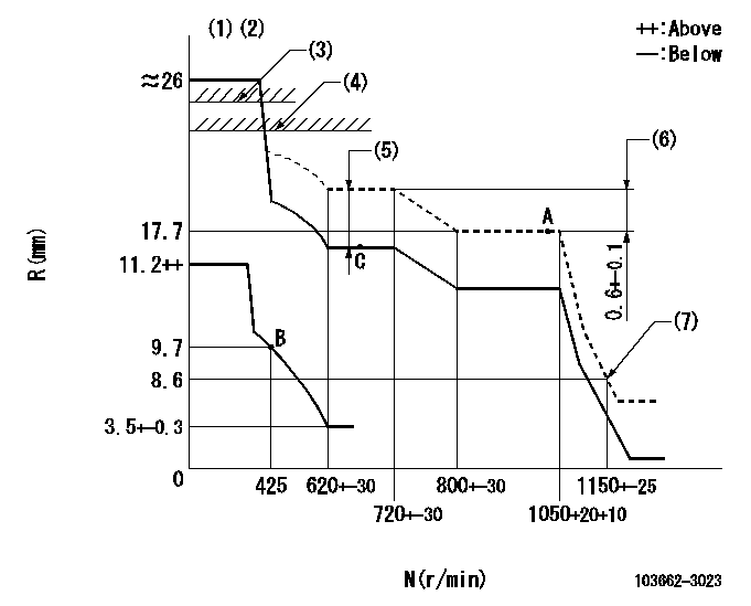
N:Pump speed
R:Rack position (mm)
(1)Minimum - maximum speed specification
(2)Target notch: K
(3)Stop lever's normal position setting: R1
(4)RACK LIMIT: RAL
(5)Boost compensator stroke: BCL
(6)Rack difference between N = N1 and N = N2
(7)Idle sub spring setting: L1.
----------
K=20 R1=19.9+0.5mm RAL=18.9+0.2mm BCL=4.4+-0.1mm N1=1050r/min N2=650r/min L1=8.6-0.5mm
----------
----------
K=20 R1=19.9+0.5mm RAL=18.9+0.2mm BCL=4.4+-0.1mm N1=1050r/min N2=650r/min L1=8.6-0.5mm
----------
Speed control lever angle

F:Full speed
----------
----------
a=20deg+-5deg
----------
----------
a=20deg+-5deg
0000000901
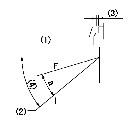
F:Full load
I:Idle
(1)Use the hole at R = aa
(2)Stopper bolt setting
(3)Clearance is bb from where contacts inner stopper.
(4)Actual measurement
----------
aa=80mm bb=(2)mm
----------
a=21deg+-5deg
----------
aa=80mm bb=(2)mm
----------
a=21deg+-5deg
Stop lever angle
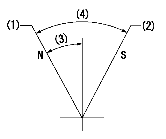
N:Pump normal
S:Stop the pump.
(1)Rack position = aa
(2)Rack position bb, pump speed cc
(3)(Actual measurement)
(4)(Actual measurement)
----------
aa=19.9+0.5mm bb=2-0.2mm cc=0r/min
----------
----------
aa=19.9+0.5mm bb=2-0.2mm cc=0r/min
----------
Information:
1. Remove bolts (1) and the washers that hold rocker shaft assembly (2) in position.2. Remove rocker shaft assembly (2). Remove the O-ring seal from the rear rocker arm support bracket.3. Put identification marks on push rods (3) as to their location in the engine. Remove the push rods.Install Rocker Shaft Assembly & Push Rods
1. Install push rods (1). Make sure they are in their original location in the engine and in position in the valve lifters.
Loosen the adjusting screws on the rocker arms. This will prevent a bent valve or push rod during installation of the rocker shaft assembly.
2. Install a new O-ring seal in the rear rocker arm support bracket. Put 2P2506 Thread Lubricant on all of the bolts that hold the rocker shaft assembly in position except for the bolt that goes through the rear rocker arm support bracket.3. Put rocker shaft assembly (2) in position on the engine. Make sure the dowels in the support bracket are in alignment with the dowel holes in the cylinder head. Make sure the rocker arms are engaged with the push rods.4. Install the bolts and washers that hold the rocker shaft assembly in position. Tighten them until they are finger tight.
3304 Engine Sequence
3306 Engine Sequence5. Tighten the bolts that hold the rocker shaft as follows:a. Tighten the bolts in number sequence to a torque of 156 N m (115 lb ft).b. Tighten the bolts in number sequence to a torque of 250 17 N m (185 13 lb ft).c. Tighten the bolts again in number sequence to a torque of 250 17 N m (185 13 lb ft).6. See "Valve Clearance Setting" in Testing & Adjusting. Make an adjustment to the valves so the intake valves have 0.38 mm (.015 in) clearance and the exhaust valves have 0.64 mm (.025 in) clearance. Tighten the locknuts for the adjusting screws to a torque of 29 7 N m (21 5 lb ft).End By:a. install valve cover
Have questions with 103662-3023?
Group cross 103662-3023 ZEXEL
Mitsubishi-Heav
Komatsu
103662-3023
INJECTION-PUMP ASSEMBLY
SA6D170
SA6D170