Information injection-pump assembly
BOSCH
9 400 616 252
9400616252
ZEXEL
102672-1360
1026721360
NIIGATA-URAWA
41047010C
41047010c

Rating:
Service parts 102672-1360 INJECTION-PUMP ASSEMBLY:
1.
_
5.
AUTOM. ADVANCE MECHANIS
6.
COUPLING PLATE
7.
COUPLING PLATE
8.
_
9.
_
11.
Nozzle and Holder
12.
Open Pre:MPa(Kqf/cm2)
15.
NOZZLE SET
Cross reference number
BOSCH
9 400 616 252
9400616252
ZEXEL
102672-1360
1026721360
NIIGATA-URAWA
41047010C
41047010c
Zexel num
Bosch num
Firm num
Name
102672-1360
9 400 616 252
41047010C NIIGATA-URAWA
INJECTION-PUMP ASSEMBLY
6L16 K 14BQ INJECTION PUMP ASSY PE3-8B PE
6L16 K 14BQ INJECTION PUMP ASSY PE3-8B PE
Calibration Data:
Adjustment conditions
Test oil
1404 Test oil ISO4113 or {SAEJ967d}
1404 Test oil ISO4113 or {SAEJ967d}
Test oil temperature
degC
40
40
45
Nozzle
105000-1190
Bosch type code
DN7SD64
Nozzle holder
105031-2010
Bosch type code
KB56SD273
Opening pressure
MPa
11.8
Opening pressure
kgf/cm2
120
Injection pipe
Outer diameter - inner diameter - length (mm) mm 6-1.6-550
Outer diameter - inner diameter - length (mm) mm 6-1.6-550
Overflow valve
132424-0620
Overflow valve opening pressure
kPa
157
123
191
Overflow valve opening pressure
kgf/cm2
1.6
1.25
1.95
Tester oil delivery pressure
kPa
157
157
157
Tester oil delivery pressure
kgf/cm2
1.6
1.6
1.6
Direction of rotation (viewed from drive side)
Right R
Right R
Injection timing adjustment
Direction of rotation (viewed from drive side)
Right R
Right R
Injection order
1-3-5-6-
4-2
Pre-stroke
mm
3
2.95
3.05
Beginning of injection position
Drive side NO.1
Drive side NO.1
Difference between angles 1
Cal 1-3 deg. 60 59.5 60.5
Cal 1-3 deg. 60 59.5 60.5
Difference between angles 2
Cal 1-5 deg. 120 119.5 120.5
Cal 1-5 deg. 120 119.5 120.5
Difference between angles 3
Cal 1-6 deg. 180 179.5 180.5
Cal 1-6 deg. 180 179.5 180.5
Difference between angles 4
Cal 1-4 deg. 240 239.5 240.5
Cal 1-4 deg. 240 239.5 240.5
Difference between angles 5
Cyl.1-2 deg. 300 299.5 300.5
Cyl.1-2 deg. 300 299.5 300.5
Injection quantity adjustment
Adjusting point
A
Rack position
14.5
Pump speed
r/min
600
600
600
Average injection quantity
mm3/st.
309
300
318
Max. variation between cylinders
%
0
-3
3
Basic
*
Fixing the lever
*
Injection quantity adjustment_02
Adjusting point
B
Rack position
16
Pump speed
r/min
500
500
500
Average injection quantity
mm3/st.
322
310
334
Max. variation between cylinders
%
0
-4
4
Fixing the lever
*
Injection quantity adjustment_03
Adjusting point
C
Rack position
10
Pump speed
r/min
500
500
500
Average injection quantity
mm3/st.
144
135.5
152.5
Max. variation between cylinders
%
0
-6
6
Fixing the lever
*
Injection quantity adjustment_04
Adjusting point
D
Rack position
6.5+-0.5
Pump speed
r/min
500
500
500
Average injection quantity
mm3/st.
40
36
44
Max. variation between cylinders
%
0
-10
10
Fixing the lever
*
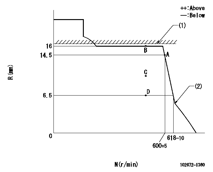
Test data Ex:
Governor adjustment

N:Pump speed
R:Rack position (mm)
(1)RACK LIMIT: RAL
(2)Beginning of idle sub spring operation: L1
----------
RAL=16.5+0.2mm L1=5.5-0.5mm
----------
----------
RAL=16.5+0.2mm L1=5.5-0.5mm
----------
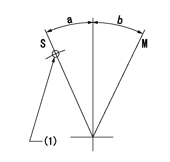
Speed control lever angle

M:Maximum speed
S:Stop
(1)Use the hole at R = aa
----------
aa=120mm
----------
a=32deg+-3deg b=(35deg)
----------
aa=120mm
----------
a=32deg+-3deg b=(35deg)
Timing setting

(1)Pump vertical direction
(2)Position of pump side coupling's reamer bolt hole at No 1 cylinder's beginning of injection
(3)-
(4)-
----------
----------
a=(50deg)
----------
----------
a=(50deg)
Information:
2. Remove six bolts (1) on radiator cover (2). 3. Loosen clamp (3) and clamp (4) and disconnect hoses. Remove two bolts (5) and remove fan guard (6). 4. Disconnect hose (8) and hose (9) from bottom of radiator y-pipe. Remove eight bolts (7) from fan shroud and move shroud toward engine to allow access to fan. 5. Remove six bolts (10) remove fan and spacer (11). Remove shroud assembly (12). 6. Loosen two bolts (13) on alternator to remove belts (14). Remove four bolts (15) on fan drive (16) and remove fan drive. The following steps are for the installation of the fan drive7. Place fan drive (16) in position and install four bolts (15).8. Place belts (14) on fan drive pulley and around the alternator pulley. Use a belt tension gauge such as a Borroughs BT-33-95 Gauge to check the belt tension. Adjust a new belt to a gauge reading of 534 22 N m (120 5 lb ft). Adjust a used belt to a gauge reading of 400 44 N m (90 10 lb ft). Tighten two bolts (13) on the alternator when belts are under tension.9. Place shroud assembly (12) into position against the engine and install fan and spacer.10. Mount shroud assembly (12) to brackets around radiator with eight bolts (7).11. Connect hoses (8) and (9) to proper position on y-pipe at the bottom of the radiator.12. Install fan guard (6) with two bolts (5).13. Connect two hoses with clamps (3) and (4).14. Install radiator cover (2) with six bolts (1).15. Fill cooling system. See the Maintenance Manual.Disassemble And Assemble Fan Drive
Start By:a. remove fan drive 1. Remove dust cover (1). 2. Remove bolt (2) and plate (3). Remove six bolts (4) and remove pulley (5) off of hub (10). Slide hub off of bracket (6). 3. Remove cone bearing (7), cup bearing (8), spacer (9), cup bearing (11), cone bearing (13), seal (12) and spacer (14) out of hub. The following steps are for the assembly of the fan drive.4. Install spacer (14) onto bracket (6).5. Install cup bearing (11) and cone bearing (13) into hub (10).6. Install seal (12) as shown in Illustration.7. Install spacer (9), cup bearing (8) and cone bearing (7) into hub (10).8. Place hub assembly onto bracket shaft.9. Install plate (3) and bolt (2) into shaft and place dust cover (1) on shaft.10. Install pulley (5).End By:a. install fan drive
Start By:a. remove fan drive 1. Remove dust cover (1). 2. Remove bolt (2) and plate (3). Remove six bolts (4) and remove pulley (5) off of hub (10). Slide hub off of bracket (6). 3. Remove cone bearing (7), cup bearing (8), spacer (9), cup bearing (11), cone bearing (13), seal (12) and spacer (14) out of hub. The following steps are for the assembly of the fan drive.4. Install spacer (14) onto bracket (6).5. Install cup bearing (11) and cone bearing (13) into hub (10).6. Install seal (12) as shown in Illustration.7. Install spacer (9), cup bearing (8) and cone bearing (7) into hub (10).8. Place hub assembly onto bracket shaft.9. Install plate (3) and bolt (2) into shaft and place dust cover (1) on shaft.10. Install pulley (5).End By:a. install fan drive
Have questions with 102672-1360?
Group cross 102672-1360 ZEXEL
Niigata-Urawa
102672-1360
9 400 616 252
41047010C
INJECTION-PUMP ASSEMBLY
6L16
6L16