Information injection-pump assembly
ZEXEL
101991-1150
1019911150
MITSUBISHI
3196180031
3196180031

Rating:
Service parts 101991-1150 INJECTION-PUMP ASSEMBLY:
1.
_
7.
COUPLING PLATE
8.
_
9.
_
11.
Nozzle and Holder
31161-18000
12.
Open Pre:MPa(Kqf/cm2)
11.8{120}

15.
NOZZLE SET
Cross reference number
ZEXEL
101991-1150
1019911150
MITSUBISHI
3196180031
3196180031
Zexel num
Bosch num
Firm num
Name
101991-1150
3196180031 MITSUBISHI
INJECTION-PUMP ASSEMBLY
10DC60 * K
10DC60 * K
Calibration Data:
Adjustment conditions
Test oil
1404 Test oil ISO4113 or {SAEJ967d}
1404 Test oil ISO4113 or {SAEJ967d}
Test oil temperature
degC
40
40
45
Nozzle
105780-0020
Bosch type code
NP-DN4SD24T
Nozzle holder
105031-2010
Bosch type code
NP-KB56SD273
Opening pressure
MPa
11.8
Opening pressure
kgf/cm2
120
Injection pipe
Outer diameter - inner diameter - length (mm) mm 6-1.6-550
Outer diameter - inner diameter - length (mm) mm 6-1.6-550
Overflow valve
132424-0620
Overflow valve opening pressure
kPa
157
123
191
Overflow valve opening pressure
kgf/cm2
1.6
1.25
1.95
Tester oil delivery pressure
kPa
157
157
157
Tester oil delivery pressure
kgf/cm2
1.6
1.6
1.6
Direction of rotation (viewed from drive side)
Right R
Right R
Injection timing adjustment
Direction of rotation (viewed from drive side)
Right R
Right R
Injection order
1-2-7-8-
5-6-3-4-
9-10
Pre-stroke
mm
2.1
2.05
2.15
Beginning of injection position
Governor side NO.1
Governor side NO.1
Difference between angles 1
Cyl.1-2 deg. 45 44.5 45.5
Cyl.1-2 deg. 45 44.5 45.5
Difference between angles 2
Cal 1-7 deg. 72 71.5 72.5
Cal 1-7 deg. 72 71.5 72.5
Difference between angles 3
Cal 1-8 deg. 117 116.5 117.5
Cal 1-8 deg. 117 116.5 117.5
Difference between angles 4
Cal 1-5 deg. 144 143.5 144.5
Cal 1-5 deg. 144 143.5 144.5
Difference between angles 5
Cal 1-6 deg. 189 188.5 189.5
Cal 1-6 deg. 189 188.5 189.5
Difference between angles 6
Cal 1-3 deg. 216 215.5 216.5
Cal 1-3 deg. 216 215.5 216.5
Difference between angles 7
Cal 1-4 deg. 261 260.5 261.5
Cal 1-4 deg. 261 260.5 261.5
Difference between angles 8
Cal 1-9 deg. 288 287.5 288.5
Cal 1-9 deg. 288 287.5 288.5
Difference between angles 9
Cal 1-10 deg. 333 332.5 333.5
Cal 1-10 deg. 333 332.5 333.5
Injection quantity adjustment
Adjusting point
A
Rack position
12.5
Pump speed
r/min
800
800
800
Average injection quantity
mm3/st.
130
126.1
133.9
Max. variation between cylinders
%
0
-3
3
Basic
*
Fixing the lever
*
Injection quantity adjustment_02
Adjusting point
B
Rack position
12
Pump speed
r/min
900
900
900
Average injection quantity
mm3/st.
123
118
128
Max. variation between cylinders
%
0
-4
4
Fixing the rack
*
Injection quantity adjustment_03
Adjusting point
C
Rack position
11.3
Pump speed
r/min
750
750
750
Average injection quantity
mm3/st.
110
105.5
114.5
Max. variation between cylinders
%
0
-4
4
Fixing the rack
*
Injection quantity adjustment_04
Adjusting point
D
Rack position
7.2+-0.5
Pump speed
r/min
250
250
250
Average injection quantity
mm3/st.
20
17
23
Max. variation between cylinders
%
0
-15
15
Fixing the rack
*
Timer adjustment
Pump speed
r/min
250+-50
Advance angle
deg.
0
0
0
Remarks
Start
Start
Timer adjustment_02
Pump speed
r/min
600
Advance angle
deg.
3
2.5
3.5
Timer adjustment_03
Pump speed
r/min
900
Advance angle
deg.
5.5
5
6
Timer adjustment_04
Pump speed
r/min
1200
Advance angle
deg.
8
7.5
8.5
Remarks
Finish
Finish
Test data Ex:
Governor adjustment
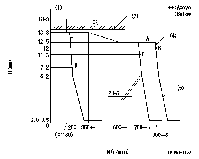
N:Pump speed
R:Rack position (mm)
(1)Target notch: K
(2)RACK LIMIT: RAL
(3)Control lever's minimum speed setting
(4)Control lever's full speed setting
(5)Idle sub spring setting: L1.
----------
K=5 RAL=13.3+0.5mm L1=6.2-0.2mm
----------
----------
K=5 RAL=13.3+0.5mm L1=6.2-0.2mm
----------
Speed control lever angle
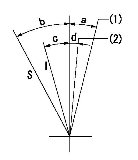
I:Idle
S:Stop
(1)Set the pump speed at aa
(2)Set the pump speed at bb.
----------
aa=900r/min bb=750r/min
----------
a=13deg+-5deg b=32deg+-3deg c=22deg+-5deg d=5deg+-5deg
----------
aa=900r/min bb=750r/min
----------
a=13deg+-5deg b=32deg+-3deg c=22deg+-5deg d=5deg+-5deg
Information:
face="Courier New" size=-1>0.0% 0.0% 0.0%
This is a 5.0-hour job for Group 2
Product smu/age whichever comes first Caterpillar Dealer Suggested Customer Suggested
Parts % Labor Hrs% Parts % Labor Hrs% Parts % Labor Hrs%
*******Group 3*******
0-3000 hrs,
0-24 mo 100.0% 100.0% 0.0% 0.0% 0.0% 0.0%
This is a 5.0-hour job for Group 3
Product smu/age whichever comes first Caterpillar Dealer Suggested Customer Suggested
Parts % Labor Hrs% Parts % Labor Hrs% Parts % Labor Hrs%
*******Group 4*******
0-3000 hrs,
0-24 mo 100.0% 100.0% 0.0% 0.0% 0.0% 0.0%
This is a 5.0-hour job for Group 4
Product smu/age whichever comes first Caterpillar Dealer Suggested Customer Suggested
Parts % Labor Hrs% Parts % Labor Hrs% Parts % Labor Hrs%
*******Group 5*******
0-3000 hrs,
0-24 mo 100.0% 100.0% 0.0% 0.0% 0.0% 0.0%
This is a 5.0-hour job for Group 5
PARTS DISPOSITION
Handle the parts in accordance with your Warranty Bulletin on warranty parts handling.
Rework Procedure
Engine Injector Change:
First identify which level of injector you currently have in your engine and establish which is the latest injector to replace it.
To remove and replace the injectors use the following Disassembly and Assembly Instructions.
C6.6 Caterpillar Industrial Engines: Install and Remove procedure RENR9722
C6.6 Caterpillar Built Machine: Install and Remove procedure KENR6081
Engine Reflash:
To update the flash file follow the procedure below. Refer to TMI or SISWeb for the latest flash file.
Tools Required:
PC or laptop with CAT ET installed and licensed (Version 2007A minimum) Communication Adaptor with diagnostic connector.
Flash File procedure:
Process:
1. Download the correct flash file from TMI or SISWeb.
2. Save the correct flash file to your local hard drive.
3. Connect to the ECM using Service Tool (CAT ET).
4. Make sure the ECM is powered up (Check that Red light on Comm. Adaptor is illuminated).
5. Go to "Winflash" or "Flash Memory".
6. CAT ET re-connect to the ECM.
7. Using the browse function in the top right hand corner, select the new flash file previously saved to hard drive.
8. Select "Begin Flash" (bottom right hand corner).
9. Once Flashing is complete select "CAT ET".
10. The Personality Module Mismatch should appear, select the ok button.
11. The factory password screen should now appear.
12. Use https://fps.cat.com to obtain factory passwords.
13. Enter Factory Passwords.
14. CAT ET High Level Configuration screen should be displayed.
15. Re-flash complete.
Have questions with 101991-1150?
Group cross 101991-1150 ZEXEL
Mitsubishi
101991-1150
3196180031
INJECTION-PUMP ASSEMBLY
10DC60
10DC60