Information injection-pump assembly
ZEXEL
101902-0000
1019020000
ISUZU
1156010271
1156010271
Rating:
Cross reference number
ZEXEL
101902-0000
1019020000
ISUZU
1156010271
1156010271
Zexel num
Bosch num
Firm num
Name
Calibration Data:
Adjustment conditions
Test oil
1404 Test oil ISO4113 or {SAEJ967d}
1404 Test oil ISO4113 or {SAEJ967d}
Test oil temperature
degC
40
40
45
Nozzle and nozzle holder
105780-8140
Bosch type code
EF8511/9A
Nozzle
105780-0000
Bosch type code
DN12SD12T
Nozzle holder
105780-2080
Bosch type code
EF8511/9
Opening pressure
MPa
17.2
Opening pressure
kgf/cm2
175
Injection pipe
Outer diameter - inner diameter - length (mm) mm 6-2-600
Outer diameter - inner diameter - length (mm) mm 6-2-600
Overflow valve
134424-0020
Overflow valve opening pressure
kPa
157
123
191
Overflow valve opening pressure
kgf/cm2
1.6
1.25
1.95
Tester oil delivery pressure
kPa
157
157
157
Tester oil delivery pressure
kgf/cm2
1.6
1.6
1.6
Direction of rotation (viewed from drive side)
Right R
Right R
Injection timing adjustment
Direction of rotation (viewed from drive side)
Right R
Right R
Injection order
R: right hand row, L: left hand row 1L4R9L8R 5L2R11L1 0R3L6R7L
R: right hand row, L: left hand row 1L4R9L8R 5L2R11L1 0R3L6R7L
Pre-stroke
mm
4.4
4.35
4.45
Beginning of injection position
Governor side NO.1
Governor side NO.1
Difference between angles 1
Cal 1-4 deg. 15 14.5 15.5
Cal 1-4 deg. 15 14.5 15.5
Difference between angles 2
Cal 1-9 deg. 60 59.5 60.5
Cal 1-9 deg. 60 59.5 60.5
Difference between angles 3
Cal 1-8 deg. 75 74.5 75.5
Cal 1-8 deg. 75 74.5 75.5
Difference between angles 4
Cal 1-5 deg. 120 119.5 120.5
Cal 1-5 deg. 120 119.5 120.5
Difference between angles 5
Cyl.1-2 deg. 135 134.5 135.5
Cyl.1-2 deg. 135 134.5 135.5
Difference between angles 6
Cal 1-11 deg. 180 179.5 180.5
Cal 1-11 deg. 180 179.5 180.5
Difference between angles 7
Cal 1-10 deg. 195 194.5 195.5
Cal 1-10 deg. 195 194.5 195.5
Difference between angles 8
Cal 1-3 deg. 240 239.5 240.5
Cal 1-3 deg. 240 239.5 240.5
Difference between angles 9
Cal 1-6 deg. 255 254.5 255.5
Cal 1-6 deg. 255 254.5 255.5
Difference between angles 10
Cal 1-7 deg. 300 299.5 300.5
Cal 1-7 deg. 300 299.5 300.5
Difference between angles 11
Cal 1-12 deg. 315 314.5 315.5
Cal 1-12 deg. 315 314.5 315.5
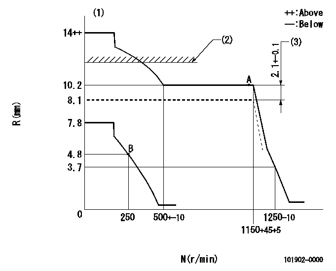
Injection quantity adjustment
Adjusting point
A
Rack position
10.2
Pump speed
r/min
1150
1150
1150
Average injection quantity
mm3/st.
128.5
127.5
129.5
Max. variation between cylinders
%
0
-2
2
Basic
*
Fixing the lever
*
Boost pressure
kPa
73.3
73.3
Boost pressure
mmHg
550
550
Injection quantity adjustment_02
Adjusting point
B
Rack position
4.8+-0.5
Pump speed
r/min
250
250
250
Average injection quantity
mm3/st.
10
8.6
11.4
Max. variation between cylinders
%
0
-13
13
Fixing the rack
*
Boost pressure
kPa
0
0
0
Boost pressure
mmHg
0
0
0
Boost compensator adjustment
Pump speed
r/min
550
550
550
Rack position
8.1
Boost pressure
kPa
10.7
8
13.4
Boost pressure
mmHg
80
60
100
Boost compensator adjustment_02
Pump speed
r/min
550
550
550
Rack position
10.2
Boost pressure
kPa
56
45.3
66.7
Boost pressure
mmHg
420
340
500
Test data Ex:
Governor adjustment
N:Pump speed
R:Rack position (mm)
(1)Target notch: K
(2)Excessive fuel setting for starting using boost compensator lever: SXL
(3)Boost compensator stroke
----------
K=5 SXL=10.4+0.2mm
----------
----------
K=5 SXL=10.4+0.2mm
----------
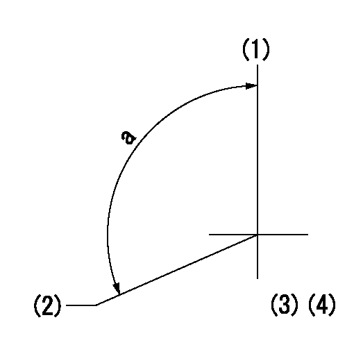
Speed control lever angle
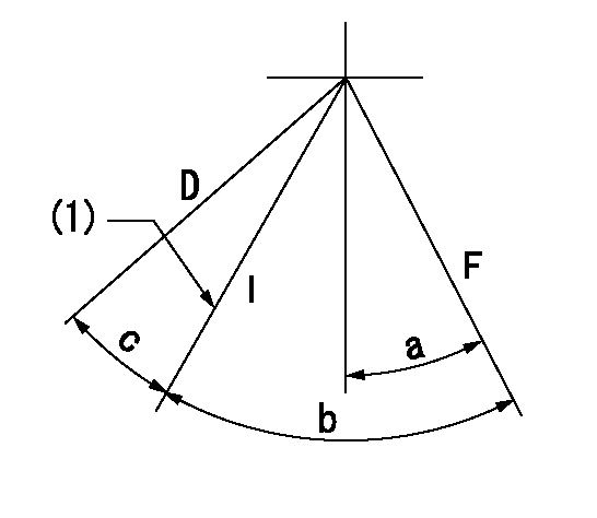
F:Full speed
I:Idle
D:Dead point
(1)Stopper bolt setting
----------
----------
a=22deg+-5deg b=32deg+-5deg c=0deg+6deg
----------
----------
a=22deg+-5deg b=32deg+-5deg c=0deg+6deg
Stop lever angle

N:Pump normal
S:Stop the pump.
----------
----------
a=0deg+-5deg b=53deg+-5deg
----------
----------
a=0deg+-5deg b=53deg+-5deg
0000001101
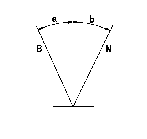
N:Normal
B:When boosted
----------
----------
a=(10deg) b=(15deg)
----------
----------
a=(10deg) b=(15deg)
Timing setting
(1)Pump vertical direction
(2)Position of gear shaft's key groove at No 1 cylinder's beginning of injection
(3)B.T.D.C.: aa
(4)-
----------
aa=16deg
----------
a=(120deg)
----------
aa=16deg
----------
a=(120deg)
Information:
Core Management
Please refer to the Caterpillar® Core Management Information System (CMIS 2) Parts Information application describing all reman part/CAF and related information. Also refer to other CMIS 2 inquiry applications such as Customer Profiles, Inspection Reason Codes, Inspection Line Inquiry, Add Charge Information, Entitlement Activity, Entitlement Inquiry, CCR Inquiry, CCR Entry, Shipment Processing; Process Packaging Grief; and Reporting to properly manage core returns and monitor inspection performance. This information will be available to all dealers worldwide after your CMIS 2 conversion date. In the meantime, please continue to use the current CMIS Entitlement Parts Inquiry Screen describing the list of parts in a Core Acceptability Family (CAF) and related part number detail.
For the latest updates of Reman Policies and Core Management (SELD0122), Core Management Systems & Operations Procedures (SELD0040), and Shipping Instructions (SELD0039), go to the Reman Dealer website https://reman.cat.com
If you have any questions regarding core return processing, feel free to call Corinth toll free at (800) 537-2928. For assistance with technical questions, call the Peoria Reman Customer Satisfaction Hot Line also toll free at (888) 88-REMAN or use our E-mail address--Reman_Help.
RWSmith
Remanufactured Products Group
LC-2148 (309) 675-5445