Information injection-pump assembly
BOSCH
9 400 616 238
9400616238
ZEXEL
101901-4291
1019014291
ISUZU
1156017020
1156017020
Rating:
Service parts 101901-4291 INJECTION-PUMP ASSEMBLY:
1.
_
2.
FUEL INJECTION PUMP
3.
GOVERNOR
4.
SUPPLY PUMP
7.
COUPLING PLATE
8.
_
9.
_
10.
NOZZLE AND HOLDER ASSY
11.
Nozzle and Holder
12.
Open Pre:MPa(Kqf/cm2)
13.
NOZZLE-HOLDER
14.
NOZZLE
15.
NOZZLE SET
Cross reference number
BOSCH
9 400 616 238
9400616238
ZEXEL
101901-4291
1019014291
ISUZU
1156017020
1156017020
Zexel num
Bosch num
Firm num
Name
101901-4291
9 400 616 238
1156017020 ISUZU
INJECTION-PUMP ASSEMBLY
8PC1 K 14BG INJECTION PUMP ASSY PE8A PE
8PC1 K 14BG INJECTION PUMP ASSY PE8A PE
Calibration Data:
Adjustment conditions
Test oil
1404 Test oil ISO4113 or {SAEJ967d}
1404 Test oil ISO4113 or {SAEJ967d}
Test oil temperature
degC
40
40
45
Nozzle and nozzle holder
105780-8140
Bosch type code
EF8511/9A
Nozzle
105780-0000
Bosch type code
DN12SD12T
Nozzle holder
105780-2080
Bosch type code
EF8511/9
Opening pressure
MPa
17.2
Opening pressure
kgf/cm2
175
Injection pipe
Outer diameter - inner diameter - length (mm) mm 6-2-600
Outer diameter - inner diameter - length (mm) mm 6-2-600
Tester oil delivery pressure
kPa
157
157
157
Tester oil delivery pressure
kgf/cm2
1.6
1.6
1.6
Direction of rotation (viewed from drive side)
Right R
Right R
Injection timing adjustment
Direction of rotation (viewed from drive side)
Right R
Right R
Injection order
R: right hand row, L: left hand row 1L-8R-7L -3L-6R-5 L-4R-2R
R: right hand row, L: left hand row 1L-8R-7L -3L-6R-5 L-4R-2R
Pre-stroke
mm
3.2
3.15
3.25
Beginning of injection position
Opposite to the driving side NO.1
Opposite to the driving side NO.1
Difference between angles 1
Cal 1-8 deg. 45 44.5 45.5
Cal 1-8 deg. 45 44.5 45.5
Difference between angles 2
Cal 1-7 deg. 90 89.5 90.5
Cal 1-7 deg. 90 89.5 90.5
Difference between angles 3
Cal 1-3 deg. 135 134.5 135.5
Cal 1-3 deg. 135 134.5 135.5
Difference between angles 4
Cal 1-6 deg. 180 179.5 180.5
Cal 1-6 deg. 180 179.5 180.5
Difference between angles 5
Cal 1-5 deg. 225 224.5 225.5
Cal 1-5 deg. 225 224.5 225.5
Difference between angles 6
Cal 1-4 deg. 270 269.5 270.5
Cal 1-4 deg. 270 269.5 270.5
Difference between angles 7
Cyl.1-2 deg. 315 314.5 315.5
Cyl.1-2 deg. 315 314.5 315.5
Injection quantity adjustment
Adjusting point
A
Rack position
8.6
Pump speed
r/min
800
800
800
Average injection quantity
mm3/st.
86.1
85.1
87.1
Max. variation between cylinders
%
0
-2
2
Basic
*
Fixing the lever
*
Injection quantity adjustment_02
Adjusting point
C
Rack position
3.3
Pump speed
r/min
260
260
260
Average injection quantity
mm3/st.
8.6
7.2
10
Max. variation between cylinders
%
0
-15
15
Fixing the rack
*
Timer adjustment
Pump speed
r/min
950--
Advance angle
deg.
0
0
0
Remarks
Start
Start
Timer adjustment_02
Pump speed
r/min
900
Advance angle
deg.
0.5
Timer adjustment_03
Pump speed
r/min
1100
Advance angle
deg.
2.5
2
3
Timer adjustment_04
Pump speed
r/min
-
Advance angle
deg.
6
6
6
Remarks
Measure the actual speed, stop
Measure the actual speed, stop
Test data Ex:
Governor adjustment
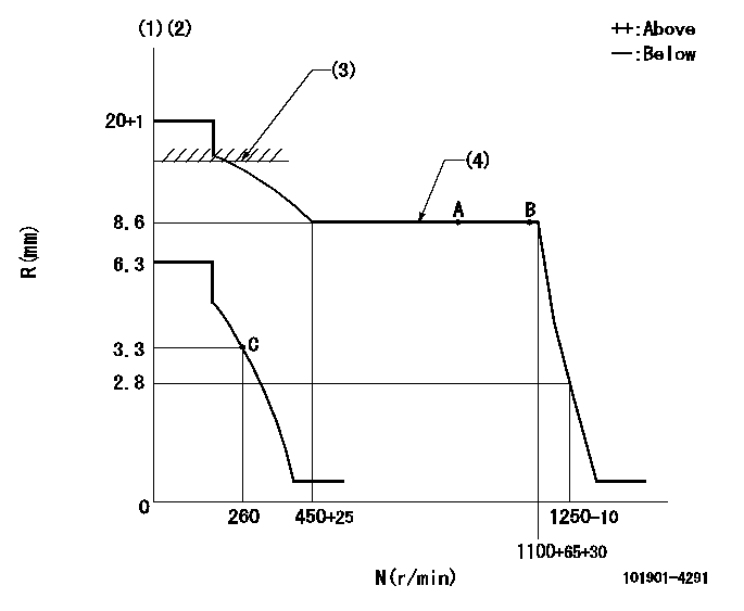
N:Pump speed
R:Rack position (mm)
(1)Target notch: K
(2)Do not operate the damper spring.
(3)RACK CAP: R1
(4)The torque control spring does not operate.
----------
K=20 R1=(17.5)mm
----------
----------
K=20 R1=(17.5)mm
----------
Speed control lever angle
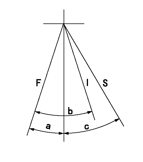
F:Full speed
I:Idle
S:Stop
----------
----------
a=15deg+-3deg b=29deg+-5deg c=32deg+-3deg
----------
----------
a=15deg+-3deg b=29deg+-5deg c=32deg+-3deg
Stop lever angle

N:Pump normal
S:Stop the pump.
----------
----------
a=19deg+-5deg b=53deg+-5deg
----------
----------
a=19deg+-5deg b=53deg+-5deg
0000001501 MICRO SWITCH
Adjustment of the micro-switch
Adjust the bolt to obtain the following lever position when the micro-switch is ON.
(1)Speed N1
(2)Rack position Ra
----------
N1=300r/min Ra=3.3mm
----------
----------
N1=300r/min Ra=3.3mm
----------
Timing setting

(1)Pump vertical direction
(2)Position of timer's threaded hole at No 1 cylinder's beginning of injection
(3)B.T.D.C.: aa
(4)-
----------
aa=15deg
----------
a=(40deg)
----------
aa=15deg
----------
a=(40deg)
Information:
1. If necessary, remove the injector clamp bolt and clamp.
Illustration 1. Remove Clamp Bolt And Clamp.2. Remove jumper tube by removing two socket head cap screws on one end and loosening the tube nut on the other end. Refer to Illustrations 2 and 3.
Illustration 2. Remove Two Cap Screws.
Illustration 3. Loosen Tube Nut.
Make sure the small seat, shown in Illustration 4, is removed. Do not allow the seat to fall into any engine cavity, which could result in damage if unintentionally left inside the engine.Also, make sure the jumper tube is kept clean at all times. Dirt or other debris can get into the engine with this tube removed and cause possible damage.
Illustration 4. Do Not Lose Or Misplace Tube Seat.3. Remove four bolts and rocker arm assembly.
Illustration 5. Remove Rocker Arm Assembly.4. Remove inlet manifold bolt, as shown in Illustration 6.
Illustration 6. Remove Manifold Bolt.5. Remove the unit injector.6. Install a new injector brass sleeve or inspect and ream the existing sleeves as outlined in Tool Operating Manual NEHS0675. It is not necessary to ream new sleeves when using this procedure.7. Install the unit injector.
Do not install the injectors "off-engine" because the injector tip will protrude from the head and be subject to damage. If the injectors are installed off-engine, make sure the bottom surface of the head is raised off the surface of the work bench.
8. Install the injector forcing cover (8). Make sure the extending portion (small dowel) is in the oil supply hole of the injector. Also make sure wear button (10) is in place.
Illustration 7. Install Injector Forcing Cover (8) With Wear Button (10).9. Place a small amount of 4C-5591 Thread Lubricant on top of the injector forcing cover's wear button (10) and on the threads of forcing bolt (4).
Complete lubrication of the wear button and forcing bolt must be maintained for each injector seating procedure. Failure to relubricate each part before seating the next injector may cause premature wear or tool damage. Also, make sure the forcing bolt turns freely and does not have any damaged threads.
Illustration 8. Put A Small Amount Of Thread Lubricant On Wear Button.10. Install the forcing bridge with three 7X-0457 Bolts (5) and three 9M-1974 Hard Washers (6). Put the two long legs of the forcing bridge in the two rocker arm shaft support holes closest to the injector. The short leg of the forcing bridge sits on the intake manifold bolt boss.
Illustration 9. Install Forcing Bridge.11. Tighten forcing bridge mounting bolts (5) to 28 7 N m, 2.9 0.7 meter kg, (21 5 lb. ft.).
Damage to the head could occur if bridge mounting bolts (5) are not tightened to the specified torque.
Illustration 10. Tighten Forcing Bridge Bolts.12. Tighten the forcing bolt finger tight.13. Use a 9U-5019 Torque Wrench and tighten the forcing bolts to 34 1.4 N m, 3.5
Have questions with 101901-4291?
Group cross 101901-4291 ZEXEL
Isuzu
Isuzu
101901-4291
9 400 616 238
1156017020
INJECTION-PUMP ASSEMBLY
8PC1
8PC1