Information injection-pump assembly
ZEXEL
101901-0680
1019010680
ISUZU
1156007010
1156007010
Rating:
Cross reference number
ZEXEL
101901-0680
1019010680
ISUZU
1156007010
1156007010
Zexel num
Bosch num
Firm num
Name
101901-0680
1156007010 ISUZU
INJECTION-PUMP ASSEMBLY
12PB1 * K
12PB1 * K
Calibration Data:
Adjustment conditions
Test oil
1404 Test oil ISO4113 or {SAEJ967d}
1404 Test oil ISO4113 or {SAEJ967d}
Test oil temperature
degC
40
40
45
Nozzle and nozzle holder
105780-8140
Bosch type code
EF8511/9A
Nozzle
105780-0000
Bosch type code
DN12SD12T
Nozzle holder
105780-2080
Bosch type code
EF8511/9
Opening pressure
MPa
17.2
Opening pressure
kgf/cm2
175
Injection pipe
Outer diameter - inner diameter - length (mm) mm 6-2-600
Outer diameter - inner diameter - length (mm) mm 6-2-600
Overflow valve
134424-0020
Overflow valve opening pressure
kPa
157
123
191
Overflow valve opening pressure
kgf/cm2
1.6
1.25
1.95
Tester oil delivery pressure
kPa
157
157
157
Tester oil delivery pressure
kgf/cm2
1.6
1.6
1.6
Direction of rotation (viewed from drive side)
Right R
Right R
Injection timing adjustment
Direction of rotation (viewed from drive side)
Right R
Right R
Injection order
R: right hand row, L: left hand row L1R4L9R8 L5R2L11R 10L3R6L7
R: right hand row, L: left hand row L1R4L9R8 L5R2L11R 10L3R6L7
Pre-stroke
mm
3.2
3.15
3.25
Beginning of injection position
Opposite to the driving side NO.1
Opposite to the driving side NO.1
Difference between angles 1
Cal 1-4 deg. 15 14.5 15.5
Cal 1-4 deg. 15 14.5 15.5
Difference between angles 2
Cal 1-9 deg. 60 59.5 60.5
Cal 1-9 deg. 60 59.5 60.5
Difference between angles 3
Cal 1-8 deg. 75 74.5 75.5
Cal 1-8 deg. 75 74.5 75.5
Difference between angles 4
Cal 1-5 deg. 120 119.5 120.5
Cal 1-5 deg. 120 119.5 120.5
Difference between angles 5
Cyl.1-2 deg. 135 134.5 135.5
Cyl.1-2 deg. 135 134.5 135.5
Difference between angles 6
Cal 1-11 deg. 180 179.5 180.5
Cal 1-11 deg. 180 179.5 180.5
Difference between angles 7
Cal 1-10 deg. 195 194.5 195.5
Cal 1-10 deg. 195 194.5 195.5
Difference between angles 8
Cal 1-3 deg. 240 239.5 240.5
Cal 1-3 deg. 240 239.5 240.5
Difference between angles 9
Cal 1-6 deg. 255 254.5 255.5
Cal 1-6 deg. 255 254.5 255.5
Difference between angles 10
Cal 1-7 deg. 300 299.5 300.5
Cal 1-7 deg. 300 299.5 300.5
Difference between angles 11
Cal 1-12 deg. 315 314.5 315.5
Cal 1-12 deg. 315 314.5 315.5
Injection quantity adjustment
Adjusting point
A
Rack position
11.7
Pump speed
r/min
1250
1250
1250
Average injection quantity
mm3/st.
89.8
87.8
91.8
Max. variation between cylinders
%
0
-4
4
Fixing the lever
*
Injection quantity adjustment_02
Adjusting point
B
Rack position
11.7
Pump speed
r/min
700
700
700
Average injection quantity
mm3/st.
84
83
85
Max. variation between cylinders
%
0
-2
2
Basic
*
Fixing the lever
*
Injection quantity adjustment_03
Adjusting point
C
Rack position
8+-0.5
Pump speed
r/min
225
225
225
Average injection quantity
mm3/st.
8
6.7
9.3
Max. variation between cylinders
%
0
-13
13
Fixing the rack
*
Injection quantity adjustment_04
Adjusting point
D
Rack position
15+-0.5
Pump speed
r/min
150
150
150
Each cylinder's injection qty
mm3/st.
95
95
Fixing the lever
*
Remarks
After startup boost setting
After startup boost setting
Timer adjustment
Pump speed
r/min
1050+-50
Advance angle
deg.
0
0
0
Remarks
Start
Start
Timer adjustment_02
Pump speed
r/min
1150
Advance angle
deg.
1.4
0.9
1.9
Timer adjustment_03
Pump speed
r/min
1250
Advance angle
deg.
3
2.5
3.5
Timer adjustment_04
Pump speed
r/min
1350
Advance angle
deg.
5
4.5
5.5
Remarks
Finish
Finish
Test data Ex:
Governor adjustment
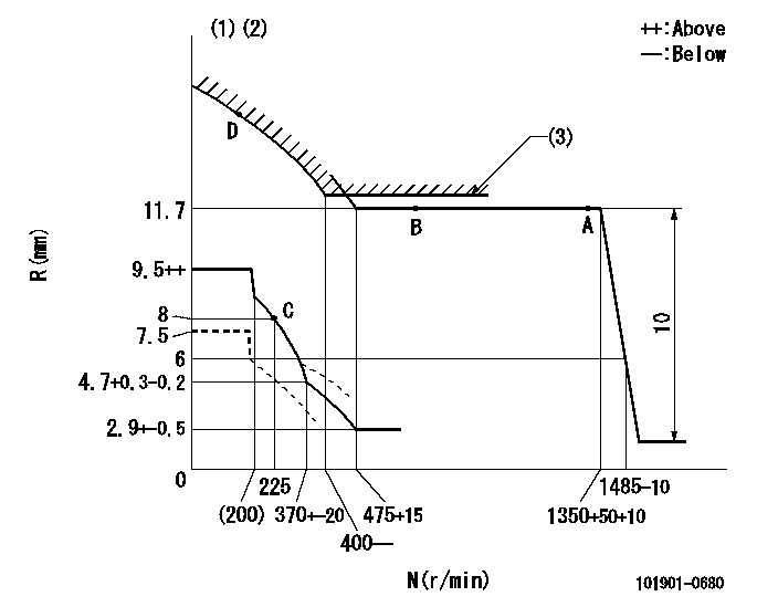
N:Pump speed
R:Rack position (mm)
(1)Beginning of damper spring operation: DL
(2)Rack limit (operating at delivery)
(3)Excess fuel setting for starting: SXL
----------
DL=6-0.5mm SXL=12.4+0.2mm
----------
----------
DL=6-0.5mm SXL=12.4+0.2mm
----------
Speed control lever angle
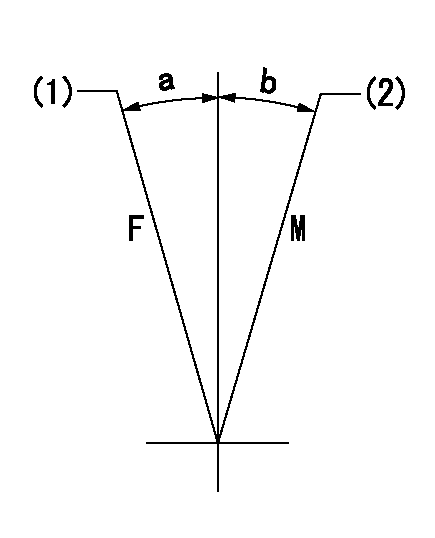
F:Full speed
M:Minimum-maximum speed
(1)Fix at full speed at delivery.
(2)Set the speed at aa. Set using two nuts.
----------
aa=741r/min
----------
a=(9deg) b=(1deg)
----------
aa=741r/min
----------
a=(9deg) b=(1deg)
0000000901
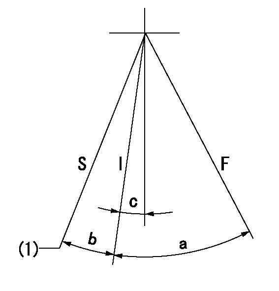
F:Full load
I:Idle
S:Stop
(1)Rack position aa (pump speed bb r/min )
----------
aa=7.5mm bb=0r/min
----------
a=32deg+-3deg b=13deg+-5deg c=1.5deg+-5deg
----------
aa=7.5mm bb=0r/min
----------
a=32deg+-3deg b=13deg+-5deg c=1.5deg+-5deg
Information:
Do not operate or work on this product unless you have read and understood the instruction and warnings in the relevant Operation and Maintenance Manuals and relevant service literature. Failure to follow the instructions or heed the warnings could result in injury or death. Proper care is your responsibility.
The following changes are adaptable to the products within the listed serial numbers, and are effective with all products after the listed serial numbers.
Illustration 1 g06602736
Soft Joint
Illustration 2 g06602738
Hard Joint
Refer to Illustration 1 and 2 for updated design from soft joint to hard joint, to mitigate the joint relaxation and air leaks.The new and former part numbers are listed in Table 1.
Table 1
Required Parts
Qty New Part Number Part Name Former Part Number(1)
1 583-3212 Exhaust Bypass 259-1436
(1) The former part number listed is for reference only and may differ.Note: Service parts are not interchangeable between the former and new part number.
Have questions with 101901-0680?
Group cross 101901-0680 ZEXEL
Isuzu
101901-0680
1156007010
INJECTION-PUMP ASSEMBLY
12PB1
12PB1