Information injection-pump assembly
BOSCH
9 400 616 231
9400616231
ZEXEL
101893-1050
1018931050
MITSUBISHI
ME066782
me066782
Rating:
Service parts 101893-1050 INJECTION-PUMP ASSEMBLY:
1.
_
7.
COUPLING PLATE
8.
_
9.
_
11.
Nozzle and Holder
31161-18000
12.
Open Pre:MPa(Kqf/cm2)
11.8{120}

15.
NOZZLE SET
Cross reference number
BOSCH
9 400 616 231
9400616231
ZEXEL
101893-1050
1018931050
MITSUBISHI
ME066782
me066782
Zexel num
Bosch num
Firm num
Name
101893-1050
9 400 616 231
ME066782 MITSUBISHI
INJECTION-PUMP ASSEMBLY
8DC6 * K
8DC6 * K
Calibration Data:
Adjustment conditions
Test oil
1404 Test oil ISO4113 or {SAEJ967d}
1404 Test oil ISO4113 or {SAEJ967d}
Test oil temperature
degC
40
40
45
Nozzle and nozzle holder
105780-8140
Bosch type code
EF8511/9A
Nozzle
105780-0000
Bosch type code
DN12SD12T
Nozzle holder
105780-2080
Bosch type code
EF8511/9
Opening pressure
MPa
17.2
Opening pressure
kgf/cm2
175
Injection pipe
Outer diameter - inner diameter - length (mm) mm 6-2-600
Outer diameter - inner diameter - length (mm) mm 6-2-600
Tester oil delivery pressure
kPa
157
157
157
Tester oil delivery pressure
kgf/cm2
1.6
1.6
1.6
Direction of rotation (viewed from drive side)
Right R
Right R
Injection timing adjustment
Direction of rotation (viewed from drive side)
Right R
Right R
Injection order
1-2-7-3-
4-5-6-8
Pre-stroke
mm
2.1
2.05
2.15
Beginning of injection position
Governor side NO.1
Governor side NO.1
Difference between angles 1
Cyl.1-2 deg. 45 44.5 45.5
Cyl.1-2 deg. 45 44.5 45.5
Difference between angles 2
Cal 1-7 deg. 90 89.5 90.5
Cal 1-7 deg. 90 89.5 90.5
Difference between angles 3
Cal 1-3 deg. 135 134.5 135.5
Cal 1-3 deg. 135 134.5 135.5
Difference between angles 4
Cal 1-4 deg. 180 179.5 180.5
Cal 1-4 deg. 180 179.5 180.5
Difference between angles 5
Cal 1-5 deg. 225 224.5 225.5
Cal 1-5 deg. 225 224.5 225.5
Difference between angles 6
Cal 1-6 deg. 270 269.5 270.5
Cal 1-6 deg. 270 269.5 270.5
Difference between angles 7
Cal 1-8 deg. 315 314.5 315.5
Cal 1-8 deg. 315 314.5 315.5
Injection quantity adjustment
Adjusting point
A
Rack position
12.5
Pump speed
r/min
800
800
800
Average injection quantity
mm3/st.
129.5
125.6
133.4
Max. variation between cylinders
%
0
-3
3
Basic
*
Fixing the lever
*
Injection quantity adjustment_02
Adjusting point
B
Rack position
12.5
Pump speed
r/min
1050
1050
1050
Average injection quantity
mm3/st.
131
127.5
134.5
Fixing the lever
*
Injection quantity adjustment_03
Adjusting point
C
Rack position
7.2+-0.5
Pump speed
r/min
200
200
200
Average injection quantity
mm3/st.
15
12
18
Max. variation between cylinders
%
0
-15
15
Fixing the rack
*
Timer adjustment
Pump speed
r/min
250+120
Advance angle
deg.
0
0
0
Remarks
Start
Start
Timer adjustment_02
Pump speed
r/min
500
Advance angle
deg.
2
1.5
2.5
Timer adjustment_03
Pump speed
r/min
900
Advance angle
deg.
5.2
4.7
5.7
Timer adjustment_04
Pump speed
r/min
1200
Advance angle
deg.
8
7.5
8.5
Timer adjustment_05
Pump speed
r/min
-
Advance angle
deg.
10
10
10
Remarks
Measure the actual speed, stop
Measure the actual speed, stop
Test data Ex:
Governor adjustment
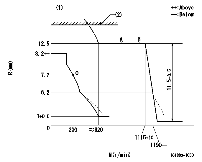
N:Pump speed
R:Rack position (mm)
(1)Damper spring setting: DL
(2)RACK LIMIT: RAL
----------
DL=4.5-0.5mm RAL=12.5+0.2mm
----------
----------
DL=4.5-0.5mm RAL=12.5+0.2mm
----------
Speed control lever angle

F:Full speed
----------
----------
a=9deg+-5deg
----------
----------
a=9deg+-5deg
0000000901

F:Full load
I:Idle
(1)Stopper bolt setting
----------
----------
a=11deg+-5deg b=41deg+-3deg
----------
----------
a=11deg+-5deg b=41deg+-3deg
Stop lever angle
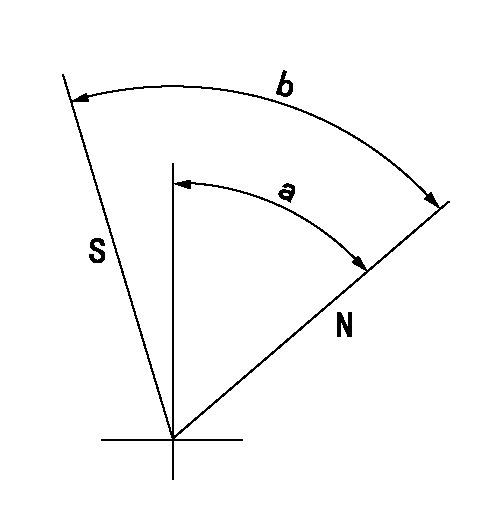
N:Pump normal
S:Stop the pump.
----------
----------
a=54deg+-5deg b=75deg+-5deg
----------
----------
a=54deg+-5deg b=75deg+-5deg
0000001501 MICRO SWITCH
Adjustment of the micro-switch
Adjust the bolt to obtain the following lever position when the micro-switch is ON.
(1)Speed N1
(2)Rack position Ra
----------
N1=325+10r/min Ra=7.2mm
----------
----------
N1=325+10r/min Ra=7.2mm
----------
Timing setting

(1)Pump vertical direction
(2)Coupling's key groove position at No 1 cylinder's beginning of injection
(3)-
(4)-
----------
----------
a=(40deg)
----------
----------
a=(40deg)
Information:
Illustration 5 g06198951
70-Pin connector
(5) Pin 4
(6) Pin 24
Illustration 6 g06198953
40-Pin connector
(7) Pin 4
(8) Pin 24
Using the appropriate terminal extraction tool, remove the red and black wires from positions 4 and 24 of the connector. Refer to Illustration 5 and 6.
Route the extracted wires out of the engine harness and insert the wires into 3E-3370 Connector Receptacle As supplied with 517-0586 Engine Harness As. Red wire in position 1 and Black wire in position 2.Note: Minor cutting of the boot may be required.
Install the Red wire from 517-0586 Engine Harness As into position 4 of the Machine Interface Connector and install the Black wire into position 24 of the connector.
Illustration 7 g06237613
70 Pin Harness
(A) Pin 4 From Machine Interface Harness Connector
(B) Pin 24 From Machine Interface Harness Connector
(C) Pyrometer Harness Interface Connector
(D) Machine Interface Connector
Illustration 8 g06237606
40 Pin Harness
(A) Pin 4 From Machine Interface Harness Connector
(B) Pin 24 From Machine Interface Harness Connector
(E) Flying Power Leads from 514-3813 Harness As to 2 Pin Connector
(F) Machine Interface Connector
If the Pyrometer Interface Harness connector is a 70 pin, Route 517-0586 Engine Harness As to the Pyrometer Harness Interface connector and install Red wire into position 70 and the Black wire into position 69. If the Pyrometer Interface Harness connector is a 40 pin, install the Red wire into pin 1 of a 2-pin receptacle and the Black wire into pin 2. This connector will then connect to G-C3 of 514-3813 Engine Harness As.
With the engine powered, use a digital multimeter to verify that 24V power is present at the Pyrometer Harness Interface connector.Installation of 510-4068 Electronic Control Gp (Pyrometer)
Attach 489-3081 Harness As to 510-4068 Electronic Control Gp (Pyrometer) and the Pyrometer Interface Connector. Using 489-3081 Engine Harness As as a gauge, temporarily install the module on an appropriate place as per the choice of installer.Installation of 505-1731 Engine Harness As
If the engine under test is a 16 cylinder instead of a 20 cylinder, 505-1731 Engine Harness As can be installed between 489-3081 Engine Harness As and 510-4068 Electronic Control Gp.Installation of 489-3081 Engine Harness As
Perform the following procedure to install 489-3081 Engine Harness As:
Install 504-3341 Engine Harness As on the service port connector of 489-3081 Engine Harness As.
Route 504-3341 Engine Harness As to a safe location before performing tests.Note: Attach 140-9442 "Y" Adapter Cable As in order to see all the machine ECMs. Connect 504-3341 Monitor Harness As to "Y", connect other leg to Machine Service port and the third leg to Communication Adapter.Overview and Configuration On Caterpillar Electronic Technician (Cat ET)
This section will describe the overview and configuration setting on Cat ET.Cat ET Screen - Standard View
Perform the following instructions once the system is installed:
Connect to communications adapter and launch Cat ET.
Illustration 9 g06198935
After connecting, under "Available ECM(s)" select "Digital Pyrometer #1".
Illustration 10 g06199349
(9) Status button
Select the "Status" (9) button in the toolbar and then the parameters of "Digital Pyrometer #1" will appear.
Selecting "Engine Cylinder Temperature - 1"
Have questions with 101893-1050?
Group cross 101893-1050 ZEXEL
Mitsubishi
101893-1050
9 400 616 231
ME066782
INJECTION-PUMP ASSEMBLY
8DC6
8DC6