Information injection-pump assembly
BOSCH
9 400 616 229
9400616229
ZEXEL
101893-1000
1018931000
MITSUBISHI
3126144010
3126144010
Rating:
Service parts 101893-1000 INJECTION-PUMP ASSEMBLY:
1.
_
7.
COUPLING PLATE
8.
_
9.
_
11.
Nozzle and Holder
12.
Open Pre:MPa(Kqf/cm2)
11.8(120)

15.
NOZZLE SET
Cross reference number
BOSCH
9 400 616 229
9400616229
ZEXEL
101893-1000
1018931000
MITSUBISHI
3126144010
3126144010
Zexel num
Bosch num
Firm num
Name
101893-1000
9 400 616 229
3126144010 MITSUBISHI
INJECTION-PUMP ASSEMBLY
8DC20 K 14BG INJECTION PUMP ASSY PE8A PE
8DC20 K 14BG INJECTION PUMP ASSY PE8A PE
Calibration Data:
Adjustment conditions
Test oil
1404 Test oil ISO4113 or {SAEJ967d}
1404 Test oil ISO4113 or {SAEJ967d}
Test oil temperature
degC
40
40
45
Nozzle and nozzle holder
105780-8140
Bosch type code
EF8511/9A
Nozzle
105780-0000
Bosch type code
DN12SD12T
Nozzle holder
105780-2080
Bosch type code
EF8511/9
Opening pressure
MPa
17.2
Opening pressure
kgf/cm2
175
Injection pipe
Outer diameter - inner diameter - length (mm) mm 6-2-600
Outer diameter - inner diameter - length (mm) mm 6-2-600
Tester oil delivery pressure
kPa
157
157
157
Tester oil delivery pressure
kgf/cm2
1.6
1.6
1.6
Direction of rotation (viewed from drive side)
Right R
Right R
Injection timing adjustment
Direction of rotation (viewed from drive side)
Right R
Right R
Injection order
1-2-7-3-
4-5-6-8
Pre-stroke
mm
2.2
2.15
2.25
Beginning of injection position
Governor side NO.1
Governor side NO.1
Difference between angles 1
Cyl.1-2 deg. 45 44.5 45.5
Cyl.1-2 deg. 45 44.5 45.5
Difference between angles 2
Cal 1-7 deg. 90 89.5 90.5
Cal 1-7 deg. 90 89.5 90.5
Difference between angles 3
Cal 1-3 deg. 135 134.5 135.5
Cal 1-3 deg. 135 134.5 135.5
Difference between angles 4
Cal 1-4 deg. 180 179.5 180.5
Cal 1-4 deg. 180 179.5 180.5
Difference between angles 5
Cal 1-5 deg. 225 224.5 225.5
Cal 1-5 deg. 225 224.5 225.5
Difference between angles 6
Cal 1-6 deg. 270 269.5 270.5
Cal 1-6 deg. 270 269.5 270.5
Difference between angles 7
Cal 1-8 deg. 315 314.5 315.5
Cal 1-8 deg. 315 314.5 315.5
Injection quantity adjustment
Adjusting point
B
Rack position
12.3
Pump speed
r/min
800
800
800
Average injection quantity
mm3/st.
111.5
108
115
Max. variation between cylinders
%
0
-3
3
Basic
*
Fixing the lever
*
Injection quantity adjustment_02
Adjusting point
C
Rack position
10.5
Pump speed
r/min
800
800
800
Average injection quantity
mm3/st.
86.4
81.9
90.9
Max. variation between cylinders
%
0
-5
5
Fixing the rack
*
Injection quantity adjustment_03
Adjusting point
D
Rack position
6.3+-0.5
Pump speed
r/min
200
200
200
Average injection quantity
mm3/st.
12.4
9.8
15
Max. variation between cylinders
%
0
-15
15
Fixing the rack
*
Injection quantity adjustment_04
Adjusting point
A
Rack position
-
Pump speed
r/min
1050
1050
1050
Average injection quantity
mm3/st.
110
106.5
113.5
Fixing the lever
*
Timer adjustment
Pump speed
r/min
250
Advance angle
deg.
0.5
Timer adjustment_02
Pump speed
r/min
350
Advance angle
deg.
1.1
Timer adjustment_03
Pump speed
r/min
500
Advance angle
deg.
1.4
0.9
1.9
Timer adjustment_04
Pump speed
r/min
800
Advance angle
deg.
4.9
4.4
5.4
Timer adjustment_05
Pump speed
r/min
1100
Advance angle
deg.
8
7.5
8.5
Timer adjustment_06
Pump speed
r/min
1200
Advance angle
deg.
9
9
10.5
Remarks
Finish
Finish
Test data Ex:
Governor adjustment
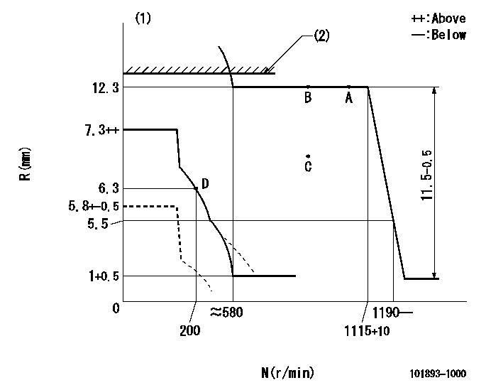
N:Pump speed
R:Rack position (mm)
(1)Beginning of damper spring operation: DL
(2)RACK LIMIT: RAL
----------
DL=5.5-0.2mm RAL=12.5+0.2mm
----------
----------
DL=5.5-0.2mm RAL=12.5+0.2mm
----------
0000000901
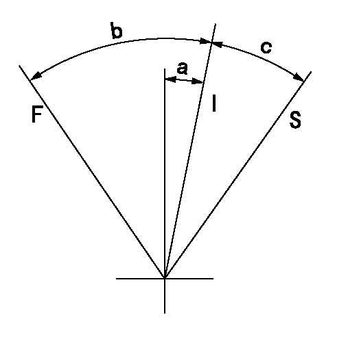
F:Full load
I:Idle
S:Stop
----------
----------
a=11deg+-5deg b=41deg+-3deg c=10deg+-3deg
----------
----------
a=11deg+-5deg b=41deg+-3deg c=10deg+-3deg
0000001501 MICRO SWITCH
Adjustment of the micro-switch
Adjust the bolt to obtain the following lever position when the micro-switch is ON.
(1)Speed N1
(2)Rack position Ra
----------
N1=325+10r/min Ra=6.3mm
----------
----------
N1=325+10r/min Ra=6.3mm
----------
Information:
Fluids/Filters Recommendation
Literature InformationThis manual should be stored in the literature holder or in the literature storage area on the machine. Immediately replace this manual if lost, damaged, or unreadable.The information contained in this document is the most current information available for fluid maintenance and service products. Special maintenance and service products may be required for some machine compartments. Refer to the Operation and Maintenance Manual for your machine for the maintenance and service requirements. Read, study, and keep this manual with the product. This manual should be read carefully before using this product for the first time and before performing maintenance.Whenever a question arises regarding your product, or this publication, consult your dealer for the latest available information.SafetyRefer to the Operation and Maintenance Manual for your machine for all safety information. Read and understand the basic safety precautions listed in the Safety Section. In addition to safety precautions, this section identifies the text and locations of warning signs used on the machine.Read and understand the applicable precautions listed in the Maintenance and Operation Sections before operating or performing lubrication, maintenance, and repair on this machine.MaintenanceRefer to the Operation and Maintenance Manual for your machine to determine all maintenance requirements.Proper maintenance and repair are essential to keep the equipment and systems operating correctly. As the owner, you are responsible for the performance of the required maintenance listed in the Owner Manual, Operation and Maintenance Manual, and Service Manual.Maintenance Interval ScheduleUse the Maintenance Interval Schedule in the Operation and Maintenance Manual for your machine to determine servicing intervals. Use the service hour meter to determine servicing intervals. Calendar intervals shown (daily, weekly, monthly, etc.) can be used instead of service hour meter intervals if calendar intervals provide more convenient servicing schedules and approximate the indicated service hour meter reading. Recommended service should always be performed at the interval that occurs first.Under extremely severe, dusty, or wet operating conditions, more frequent lubrication and/or filter changes than is specified in the maintenance intervals chart might be necessary.Following the recommended maintenance intervals reduces the risk of excessive wear and potential failures of components.Aftermarket Products and Warranty
When auxiliary devices, accessories or consumables (filters, oil, additives, catalysts, fuel, etc.) made by other manufacturers are used on Cat products, the Caterpillar warranty is not affected simply because of such use. Failures that result from the installation or usage of other manufacturers auxiliary devices, accessories or consumables, however, are not Caterpillar factory defects and therefore are NOT covered by Caterpillar's warranty.Caterpillar is not in a position to evaluate the many auxiliary devices, accessories or consumables promoted by other manufacturers and their effect on Cat products. Installation or use of such items is at the discretion of the customer who assumes ALL risks for the effects that result from this usage.Furthermore, Caterpillar does not authorize the use of its trade name, trademark, or logo in a manner which implies our endorsement of these aftermarket products.
Have questions with 101893-1000?
Group cross 101893-1000 ZEXEL
Mitsubishi
101893-1000
9 400 616 229
3126144010
INJECTION-PUMP ASSEMBLY
8DC20
8DC20