Information injection-pump assembly
BOSCH
9 400 616 226
9400616226
ZEXEL
101891-6880
1018916880
MITSUBISHI
3126140021
3126140021
Rating:
Service parts 101891-6880 INJECTION-PUMP ASSEMBLY:
1.
_
7.
COUPLING PLATE
8.
_
9.
_
11.
Nozzle and Holder
12.
Open Pre:MPa(Kqf/cm2)
11.8{120}

15.
NOZZLE SET
Cross reference number
BOSCH
9 400 616 226
9400616226
ZEXEL
101891-6880
1018916880
MITSUBISHI
3126140021
3126140021
Zexel num
Bosch num
Firm num
Name
101891-6880
9 400 616 226
3126140021 MITSUBISHI
INJECTION-PUMP ASSEMBLY
8DC20 K 14BG INJECTION PUMP ASSY PE8A PE
8DC20 K 14BG INJECTION PUMP ASSY PE8A PE
Calibration Data:
Adjustment conditions
Test oil
1404 Test oil ISO4113 or {SAEJ967d}
1404 Test oil ISO4113 or {SAEJ967d}
Test oil temperature
degC
40
40
45
Nozzle and nozzle holder
105780-8140
Bosch type code
EF8511/9A
Nozzle
105780-0000
Bosch type code
DN12SD12T
Nozzle holder
105780-2080
Bosch type code
EF8511/9
Opening pressure
MPa
17.2
Opening pressure
kgf/cm2
175
Injection pipe
Outer diameter - inner diameter - length (mm) mm 6-2-600
Outer diameter - inner diameter - length (mm) mm 6-2-600
Tester oil delivery pressure
kPa
157
157
157
Tester oil delivery pressure
kgf/cm2
1.6
1.6
1.6
Direction of rotation (viewed from drive side)
Right R
Right R
Injection timing adjustment
Direction of rotation (viewed from drive side)
Right R
Right R
Injection order
1-2-7-3-
4-5-6-8
Pre-stroke
mm
2.2
2.15
2.25
Beginning of injection position
Governor side NO.1
Governor side NO.1
Difference between angles 1
Cyl.1-2 deg. 45 44.5 45.5
Cyl.1-2 deg. 45 44.5 45.5
Difference between angles 2
Cal 1-7 deg. 90 89.5 90.5
Cal 1-7 deg. 90 89.5 90.5
Difference between angles 3
Cal 1-3 deg. 135 134.5 135.5
Cal 1-3 deg. 135 134.5 135.5
Difference between angles 4
Cal 1-4 deg. 180 179.5 180.5
Cal 1-4 deg. 180 179.5 180.5
Difference between angles 5
Cal 1-5 deg. 225 224.5 225.5
Cal 1-5 deg. 225 224.5 225.5
Difference between angles 6
Cal 1-6 deg. 270 269.5 270.5
Cal 1-6 deg. 270 269.5 270.5
Difference between angles 7
Cal 1-8 deg. 315 314.5 315.5
Cal 1-8 deg. 315 314.5 315.5
Injection quantity adjustment
Adjusting point
B
Rack position
12.5
Pump speed
r/min
800
800
800
Average injection quantity
mm3/st.
115
111.5
118.5
Max. variation between cylinders
%
0
-3
3
Basic
*
Fixing the lever
*
Injection quantity adjustment_02
Adjusting point
C
Rack position
10.5
Pump speed
r/min
800
800
800
Average injection quantity
mm3/st.
86.4
81.9
90.9
Max. variation between cylinders
%
0
-5
5
Fixing the rack
*
Injection quantity adjustment_03
Adjusting point
D
Rack position
6.3+-0.5
Pump speed
r/min
200
200
200
Average injection quantity
mm3/st.
12.4
9.8
15
Max. variation between cylinders
%
0
-15
15
Fixing the rack
*
Injection quantity adjustment_04
Adjusting point
A
Rack position
-
Pump speed
r/min
1200
1200
1200
Average injection quantity
mm3/st.
113.5
110
117
Fixing the lever
*
Timer adjustment
Pump speed
r/min
250+120
Advance angle
deg.
0
0
0
Remarks
Start
Start
Timer adjustment_02
Pump speed
r/min
500
Advance angle
deg.
1.4
0.8
2
Timer adjustment_03
Pump speed
r/min
800
Advance angle
deg.
4.2
3.6
4.8
Timer adjustment_04
Pump speed
r/min
1200
Advance angle
deg.
8
7.3
8.5
Timer adjustment_05
Pump speed
r/min
-
Advance angle
deg.
10
10
10
Remarks
Measure the actual speed, stop
Measure the actual speed, stop
Test data Ex:
Governor adjustment
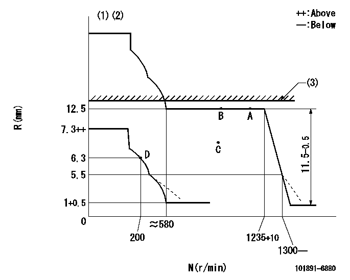
N:Pump speed
R:Rack position (mm)
(1)Beginning of damper spring operation: DL
(2)With the pump not operating, set the stopper bolt so that the rack position is R1 when the control lever is moved to the stop side.
(3)RACK LIMIT: RAL
----------
DL=5.5-0.2mm R1=5.3~6.3mm RAL=12.5+0.2mm
----------
----------
DL=5.5-0.2mm R1=5.3~6.3mm RAL=12.5+0.2mm
----------
0000000901
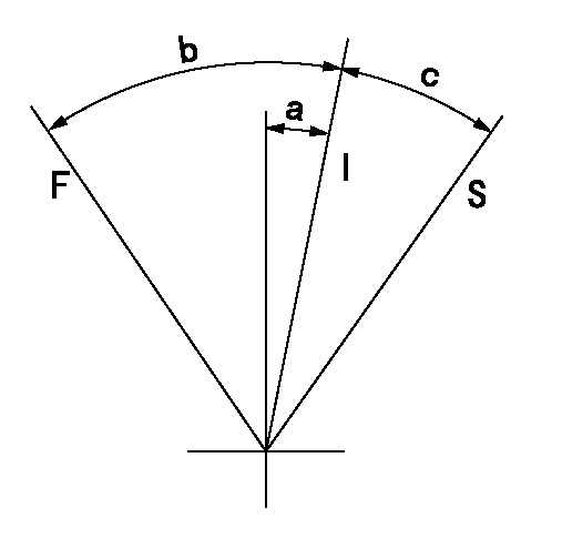
F:Full load
I:Idle
S:Stop
----------
----------
a=11deg+-5deg b=41deg+-3deg c=10deg+-3deg
----------
----------
a=11deg+-5deg b=41deg+-3deg c=10deg+-3deg
0000001501 MICRO SWITCH
Adjustment of the micro-switch
Adjust the bolt to obtain the following lever position when the micro-switch is ON.
(1)Speed N1
(2)Rack position Ra
----------
N1=325+10r/min Ra=6.3mm
----------
----------
N1=325+10r/min Ra=6.3mm
----------
Information:
Do not operate or work on this product unless you have read and understood the instruction and warnings in the relevant Operation and Maintenance Manuals and relevant service literature. Failure to follow the instructions or heed the warnings could result in injury or death. Proper care is your responsibility.
The 557-7633 Fuel Injector Gp has stayed the same, but the design level has changed to -02.The following injectors are affected by this issue:
387-9427
387-9432
387-9433
557-7633For fuel injectors leaking oil into the fuel and/or experiencing pressure too low symptoms, replace the o-ring seals and back-up rings prior to replacing the fuel injectors. If oil leakage is experienced after seal replacement, replace the fuel injector.The table below contains the parts needed for seal and ring replacement.
Table 1
Required Parts
Item Qty Part Number Part Name
1 1 109-3207 O-Ring Seal
2 2 148-2903 O-Ring Seals
3 1 149-5240 Backup Ring
4 1 293-0730 Backup Ring
Have questions with 101891-6880?
Group cross 101891-6880 ZEXEL
Mitsubishi
101891-6880
9 400 616 226
3126140021
INJECTION-PUMP ASSEMBLY
8DC20
8DC20