Information injection-pump assembly
BOSCH
9 400 616 223
9400616223
ZEXEL
101891-6640
1018916640
MITSUBISHI
3126140011
3126140011
Rating:
Include in #1:
101606-6090
as _
Cross reference number
BOSCH
9 400 616 223
9400616223
ZEXEL
101891-6640
1018916640
MITSUBISHI
3126140011
3126140011
Zexel num
Bosch num
Firm num
Name
9 400 616 223
3126140011 MITSUBISHI
INJECTION-PUMP ASSEMBLY
8DC20 K 14BG INJECTION PUMP ASSY PE8A PE
8DC20 K 14BG INJECTION PUMP ASSY PE8A PE
Calibration Data:
Adjustment conditions
Test oil
1404 Test oil ISO4113 or {SAEJ967d}
1404 Test oil ISO4113 or {SAEJ967d}
Test oil temperature
degC
40
40
45
Nozzle and nozzle holder
105780-8140
Bosch type code
EF8511/9A
Nozzle
105780-0000
Bosch type code
DN12SD12T
Nozzle holder
105780-2080
Bosch type code
EF8511/9
Opening pressure
MPa
17.2
Opening pressure
kgf/cm2
175
Injection pipe
Outer diameter - inner diameter - length (mm) mm 6-2-600
Outer diameter - inner diameter - length (mm) mm 6-2-600
Tester oil delivery pressure
kPa
157
157
157
Tester oil delivery pressure
kgf/cm2
1.6
1.6
1.6
Direction of rotation (viewed from drive side)
Right R
Right R
Injection timing adjustment
Direction of rotation (viewed from drive side)
Right R
Right R
Injection order
1-2-7-3-
4-5-6-8
Pre-stroke
mm
2.2
2.15
2.25
Beginning of injection position
Governor side NO.1
Governor side NO.1
Difference between angles 1
Cyl.1-2 deg. 45 44.5 45.5
Cyl.1-2 deg. 45 44.5 45.5
Difference between angles 2
Cal 1-7 deg. 90 89.5 90.5
Cal 1-7 deg. 90 89.5 90.5
Difference between angles 3
Cal 1-3 deg. 135 134.5 135.5
Cal 1-3 deg. 135 134.5 135.5
Difference between angles 4
Cal 1-4 deg. 180 179.5 180.5
Cal 1-4 deg. 180 179.5 180.5
Difference between angles 5
Cal 1-5 deg. 225 224.5 225.5
Cal 1-5 deg. 225 224.5 225.5
Difference between angles 6
Cal 1-6 deg. 270 269.5 270.5
Cal 1-6 deg. 270 269.5 270.5
Difference between angles 7
Cal 1-8 deg. 315 314.5 315.5
Cal 1-8 deg. 315 314.5 315.5
Injection quantity adjustment
Adjusting point
B
Rack position
12.3
Pump speed
r/min
800
800
800
Average injection quantity
mm3/st.
111.5
108
115
Max. variation between cylinders
%
0
-3
3
Basic
*
Fixing the lever
*
Injection quantity adjustment_02
Adjusting point
C
Rack position
10.5
Pump speed
r/min
800
800
800
Average injection quantity
mm3/st.
86.4
81.9
90.9
Max. variation between cylinders
%
0
-5
5
Fixing the rack
*
Injection quantity adjustment_03
Adjusting point
D
Rack position
6.3+-0.5
Pump speed
r/min
200
200
200
Average injection quantity
mm3/st.
12.4
9.8
15
Max. variation between cylinders
%
0
-15
15
Fixing the rack
*
Injection quantity adjustment_04
Adjusting point
A
Rack position
-
Pump speed
r/min
1050
1050
1050
Average injection quantity
mm3/st.
110
106.5
113.5
Fixing the lever
*
Timer adjustment
Pump speed
r/min
250+120
Advance angle
deg.
0
0
0
Remarks
Start
Start
Timer adjustment_02
Pump speed
r/min
500
Advance angle
deg.
1.4
0.8
2
Timer adjustment_03
Pump speed
r/min
800
Advance angle
deg.
4.2
3.6
4.8
Timer adjustment_04
Pump speed
r/min
1200
Advance angle
deg.
8
7.3
8.5
Timer adjustment_05
Pump speed
r/min
-
Advance angle
deg.
10
10
10
Remarks
Measure the actual speed, stop
Measure the actual speed, stop
Test data Ex:
Governor adjustment
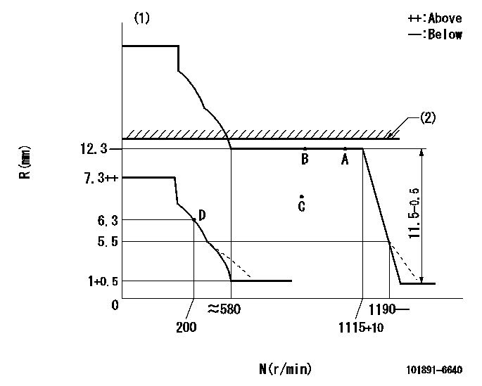
N:Pump speed
R:Rack position (mm)
(1)Beginning of damper spring operation: DL
(2)RACK LIMIT: RAL
----------
DL=5.5-0.2mm RAL=12.5+0.2mm
----------
----------
DL=5.5-0.2mm RAL=12.5+0.2mm
----------
0000000901
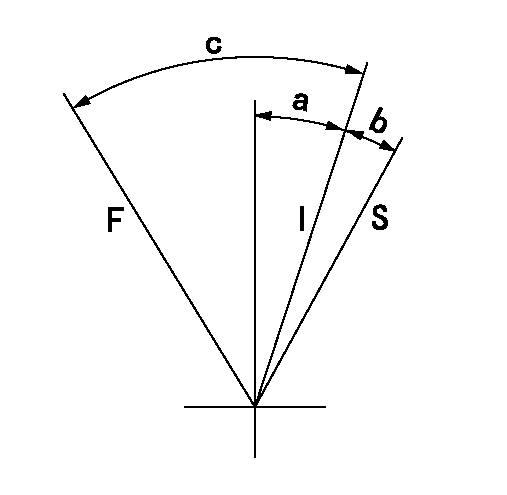
F:Full load
I:Idle
S:Stop
----------
----------
a=11deg+-5deg b=10deg+-3deg c=41deg+-3deg
----------
----------
a=11deg+-5deg b=10deg+-3deg c=41deg+-3deg
0000001501 MICRO SWITCH
Adjustment of the micro-switch
Adjust the bolt to obtain the following lever position when the micro-switch is ON.
(1)Speed N1
(2)Rack position Ra
----------
N1=325+10r/min Ra=6.3mm
----------
----------
N1=325+10r/min Ra=6.3mm
----------
Information:
Wear goggles, gloves, protective clothing, and a National Institute for Occupationsl Safety and Health (Niosh) approved P95 or N95 half-face respirator when handling a used Diesel Particulate Filter or Catalytic Converter Muffler. Failure to do so could result in personal injury.
Anyone working around or near the Cat Diesel Particulate Filter (DPF) system should be trained in the proper safety precautions and procedures including emergency shutdown, MSDS sheets detail for the necessary safety precautions and procedures required for the handling of materials. These precautions and procedures must be followed.
Service on the Cat DPF system is to be done only by trained and qualified individuals. The training includes all electrical and mechanical service.
If there is any concern about the safety of this system, clear the area immediately of all personnel. Contact the appropriate person for further instructions.