Information injection-pump assembly
BOSCH
9 400 616 220
9400616220
ZEXEL
101891-6510
1018916510
MITSUBISHI
3126185021
3126185021
Rating:
Service parts 101891-6510 INJECTION-PUMP ASSEMBLY:
1.
_
7.
COUPLING PLATE
8.
_
9.
_
11.
Nozzle and Holder
31161-18000
12.
Open Pre:MPa(Kqf/cm2)
11.8{120}

15.
NOZZLE SET
Cross reference number
BOSCH
9 400 616 220
9400616220
ZEXEL
101891-6510
1018916510
MITSUBISHI
3126185021
3126185021
Zexel num
Bosch num
Firm num
Name
101891-6510
9 400 616 220
3126185021 MITSUBISHI
INJECTION-PUMP ASSEMBLY
8DC20 K 14BG INJECTION PUMP ASSY PE8A PE
8DC20 K 14BG INJECTION PUMP ASSY PE8A PE
Calibration Data:
Adjustment conditions
Test oil
1404 Test oil ISO4113 or {SAEJ967d}
1404 Test oil ISO4113 or {SAEJ967d}
Test oil temperature
degC
40
40
45
Nozzle and nozzle holder
105780-8140
Bosch type code
EF8511/9A
Nozzle
105780-0000
Bosch type code
DN12SD12T
Nozzle holder
105780-2080
Bosch type code
EF8511/9
Opening pressure
MPa
17.2
Opening pressure
kgf/cm2
175
Injection pipe
Outer diameter - inner diameter - length (mm) mm 6-2-600
Outer diameter - inner diameter - length (mm) mm 6-2-600
Tester oil delivery pressure
kPa
157
157
157
Tester oil delivery pressure
kgf/cm2
1.6
1.6
1.6
Direction of rotation (viewed from drive side)
Right R
Right R
Injection timing adjustment
Direction of rotation (viewed from drive side)
Right R
Right R
Injection order
1-2-7-3-
4-5-6-8
Pre-stroke
mm
2.2
2.15
2.25
Beginning of injection position
Governor side NO.1
Governor side NO.1
Difference between angles 1
Cyl.1-2 deg. 45 44.5 45.5
Cyl.1-2 deg. 45 44.5 45.5
Difference between angles 2
Cal 1-7 deg. 90 89.5 90.5
Cal 1-7 deg. 90 89.5 90.5
Difference between angles 3
Cal 1-3 deg. 135 134.5 135.5
Cal 1-3 deg. 135 134.5 135.5
Difference between angles 4
Cal 1-4 deg. 180 179.5 180.5
Cal 1-4 deg. 180 179.5 180.5
Difference between angles 5
Cal 1-5 deg. 225 224.5 225.5
Cal 1-5 deg. 225 224.5 225.5
Difference between angles 6
Cal 1-6 deg. 270 269.5 270.5
Cal 1-6 deg. 270 269.5 270.5
Difference between angles 7
Cal 1-8 deg. 315 314.5 315.5
Cal 1-8 deg. 315 314.5 315.5
Injection quantity adjustment
Adjusting point
A
Rack position
14
Pump speed
r/min
500
500
500
Average injection quantity
mm3/st.
138
133.9
142.1
Max. variation between cylinders
%
0
-3
3
Basic
*
Fixing the lever
*
Injection quantity adjustment_02
Adjusting point
B
Rack position
12.3
Pump speed
r/min
1200
1200
1200
Average injection quantity
mm3/st.
121.8
117
126.6
Max. variation between cylinders
%
0
-4
4
Fixing the lever
*
Injection quantity adjustment_03
Adjusting point
C
Rack position
5.5+-0.5
Pump speed
r/min
200
200
200
Average injection quantity
mm3/st.
12.4
9.8
15
Max. variation between cylinders
%
0
-15
15
Fixing the rack
*
Timer adjustment
Pump speed
r/min
250+120
Advance angle
deg.
0
0
0
Remarks
Start
Start
Timer adjustment_02
Pump speed
r/min
500
Advance angle
deg.
1.4
0.8
2
Timer adjustment_03
Pump speed
r/min
800
Advance angle
deg.
4.2
3.6
4.8
Timer adjustment_04
Pump speed
r/min
1200
Advance angle
deg.
8
7.3
8.5
Timer adjustment_05
Pump speed
r/min
-
Advance angle
deg.
10
10
10
Remarks
Measure the actual speed, stop
Measure the actual speed, stop
Test data Ex:
Governor adjustment
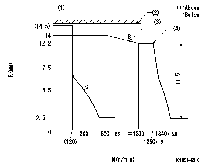
N:Pump speed
R:Rack position (mm)
(1)Target notch: K
(2)RACK LIMIT: RAL
(3)Set the torque control spring so that the injection quantity passes through point B.
(4)Torque spring does not operate.
----------
K=8 RAL=14.5+0.5mm
----------
----------
K=8 RAL=14.5+0.5mm
----------
Speed control lever angle
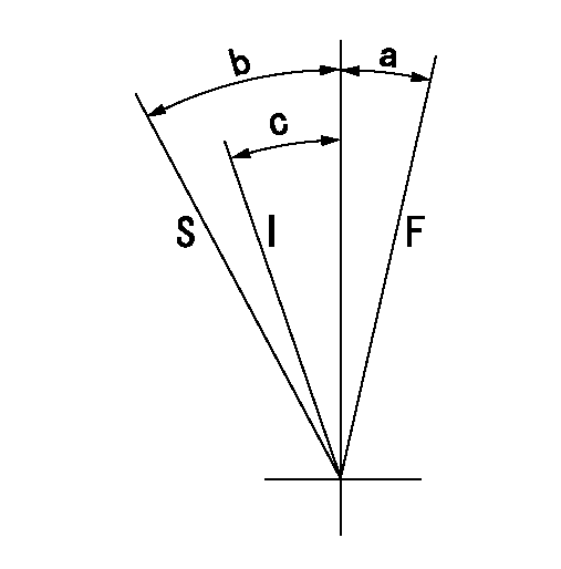
F:Full speed
I:Idle
S:Stop
----------
----------
a=(14deg) b=32deg+-3deg c=(19deg)
----------
----------
a=(14deg) b=32deg+-3deg c=(19deg)
Information:
Do not operate or work on this product unless you have read and understood the instruction and warnings in the relevant Operation and Maintenance Manuals and relevant service literature. Failure to follow the instructions or heed the warnings could result in injury or death. Proper care is your responsibility.
Table 1
Required Parts
Qty Part Number Part Name
1 420-0939 Sleeve(1)
1 420-0940 Sleeve(2)
1 420-0941 Sleeve(3)
1 420-0942 Sleeve(4)
(1) Red
(2) Silver
(3) Gold
(4) GreenSleeve Rework procedure
Illustration 1 g06360367
Typical example of an injector - without sleeve
(A) Adjustment screw
(B) Locknut
Remove and retain adjustment screw (A). Remove and discard locknut (B).
Illustration 2 g06360368
Typical example of an injector - with sleeve
(1) Sleeve
(A) Adjustment screw
Insert appropriate sleeve (1) onto adjustment screw (A).
Have questions with 101891-6510?
Group cross 101891-6510 ZEXEL
Mitsubishi
101891-6510
9 400 616 220
3126185021
INJECTION-PUMP ASSEMBLY
8DC20
8DC20