Information injection-pump assembly
BOSCH
9 400 619 802
9400619802
ZEXEL
101871-1050
1018711050
MITSUBISHI-HEAV
8506103000
8506103000
Rating:
Service parts 101871-1050 INJECTION-PUMP ASSEMBLY:
1.
_
7.
COUPLING PLATE
8.
_
9.
_
11.
Nozzle and Holder
85061-01000
12.
Open Pre:MPa(Kqf/cm2)
19.6{200}
15.
NOZZLE SET
Cross reference number
BOSCH
9 400 619 802
9400619802
ZEXEL
101871-1050
1018711050
MITSUBISHI-HEAV
8506103000
8506103000
Zexel num
Bosch num
Firm num
Name
101871-1050
9 400 619 802
8506103000 MITSUBISHI-HEAV
INJECTION-PUMP ASSEMBLY
8DV * K 14BG PE8A PE
8DV * K 14BG PE8A PE
Calibration Data:
Adjustment conditions
Test oil
1404 Test oil ISO4113 or {SAEJ967d}
1404 Test oil ISO4113 or {SAEJ967d}
Test oil temperature
degC
40
40
45
Nozzle
105780-0020
Bosch type code
DN4SD24T
Nozzle holder
105031-2010
Bosch type code
KB56SD273
Opening pressure
MPa
11.8
Opening pressure
kgf/cm2
120
Injection pipe
Outer diameter - inner diameter - length (mm) mm 6-1.6-550
Outer diameter - inner diameter - length (mm) mm 6-1.6-550
Overflow valve
132424-0620
Overflow valve opening pressure
kPa
157
123
191
Overflow valve opening pressure
kgf/cm2
1.6
1.25
1.95
Tester oil delivery pressure
kPa
157
157
157
Tester oil delivery pressure
kgf/cm2
1.6
1.6
1.6
Direction of rotation (viewed from drive side)
Left L
Left L
Injection timing adjustment
Direction of rotation (viewed from drive side)
Left L
Left L
Injection order
1-2-7-3-
4-5-6-8
Pre-stroke
mm
2.2
2.15
2.25
Beginning of injection position
Governor side NO.1
Governor side NO.1
Difference between angles 1
Cyl.1-2 deg. 45 44.5 45.5
Cyl.1-2 deg. 45 44.5 45.5
Difference between angles 2
Cal 1-7 deg. 90 89.5 90.5
Cal 1-7 deg. 90 89.5 90.5
Difference between angles 3
Cal 1-3 deg. 135 134.5 135.5
Cal 1-3 deg. 135 134.5 135.5
Difference between angles 4
Cal 1-4 deg. 180 179.5 180.5
Cal 1-4 deg. 180 179.5 180.5
Difference between angles 5
Cal 1-5 deg. 225 224.5 225.5
Cal 1-5 deg. 225 224.5 225.5
Difference between angles 6
Cal 1-6 deg. 270 269.5 270.5
Cal 1-6 deg. 270 269.5 270.5
Difference between angles 7
Cal 1-8 deg. 315 314.5 315.5
Cal 1-8 deg. 315 314.5 315.5
Injection quantity adjustment
Adjusting point
B
Rack position
13
Pump speed
r/min
900
900
900
Average injection quantity
mm3/st.
100
98
102
Max. variation between cylinders
%
0
-2
2
Basic
*
Fixing the rack
*
Injection quantity adjustment_02
Adjusting point
C
Rack position
7.2+-0.5
Pump speed
r/min
300
300
300
Average injection quantity
mm3/st.
20
17
23
Max. variation between cylinders
%
0
-15
15
Fixing the rack
*
Timer adjustment
Pump speed
r/min
400+-50
Advance angle
deg.
0
0
0
Remarks
Start
Start
Timer adjustment_02
Pump speed
r/min
600
Advance angle
deg.
1.8
1.3
2.3
Timer adjustment_03
Pump speed
r/min
900
Advance angle
deg.
4.4
3.9
4.9
Timer adjustment_04
Pump speed
r/min
1200
Advance angle
deg.
7
6.5
7.5
Timer adjustment_05
Pump speed
r/min
-
Advance angle
deg.
10
10
10
Remarks
Measure the actual speed, stop
Measure the actual speed, stop
Test data Ex:
Governor adjustment
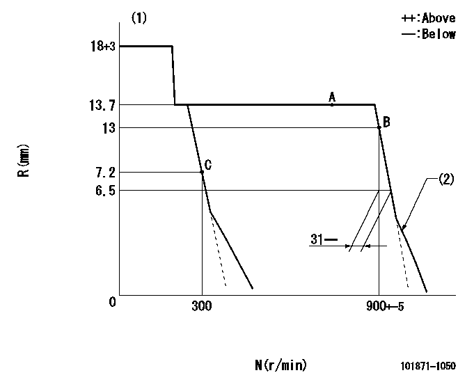
N:Pump speed
R:Rack position (mm)
(1)Target notch: K
(2)Idle sub spring setting: L1.
----------
K=3 L1=6-0.5mm
----------
----------
K=3 L1=6-0.5mm
----------
Speed control lever angle
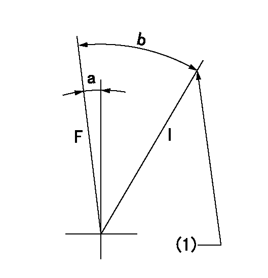
F:Full speed
I:Idle
(1)Set the pump speed at aa
----------
aa=300r/min
----------
a=(1deg) b=(26deg)
----------
aa=300r/min
----------
a=(1deg) b=(26deg)
Information:
Illustration 70 g03402776
Install 8T-5389 Elbow (12) using 238-5081 O-Ring Seal (11) and 228-7092 O-Ring Seal (13)
Illustration 71 g03701313
Install 6V-8636 Connector (17) using 214-7568 O-Ring Seal (16) and 228-7089 O-Ring Seal (18). Install 128-6841 Elbow (15) using 238-5082 O-Ring Seal (19) and 228-7092 O-Ring Seal (14).
Illustration 72 g03701321
Reconnect 209-5526 Hose As (20) to the fuel transfer pump
Illustration 73 g03701349
Install 387-7154 Tube As (21) and 387-7159 Tube As (22).
Illustration 74 g03701355
Install 416-9706 Fuel Tube (24) using 338-8439 Clip (23).
Install the remaining components that were removed during the HEUI pump replacement procedure.Installation Procedure for 511, 521, 522, 532, 541 and 552 Track Feller Bunchers
Table 10
Required parts for 532, 541, 541B , 551, 552, and 552B Track Feller Bunchers
Part Number Description Quantity
384-0607 Unit Injector Hydraulic Pump Gp 1
227-5904 O-Ring Seal 1
6V-7981 Bolt 2
6V-5839 Washer 2
387-7153 Tube As 1
387-7151 Tube As 1
6V-8629 Elbow 1
238-5081 O-Ring Seal 1
228-7092 O-Ring Seal 2
128-6841 Elbow 1
238-5082 O-Ring Seal 1
6V-8636 Connector 2
228-7089 O-Ring Seal 2
214-7568 O-Ring Seal 3
360-3679 Connector Plug 1
6V-3305 O-Ring Adapter 1
214-7567 O-Ring Seal 2
Illustration 75 g03402944
Install 6V-3305 O-Ring Adapter (2) using 214-7567 O-Ring Seal (1). Also install new 214-7567 O-Ring Seal (1) to injection actuation pressure sensor.
Illustration 76 g03402955
Install 384-0607 Unit Injector Hydraulic Pump Gp (4) using 227-5904 O-Ring Seal (3). If necessary, in order to aid in installation, rotate the pump to an 8 o'clock position when looking at the engine from the rear.
Illustration 77 g03402984
Install new 6V-7981 Bolts (5) and 6V-5839 Washers (6). Torque to 55 10 N m (41 7 lb ft)
Illustration 78 g03701359
Install the 6V-8636 Connector (12) using 214-7568 O-Ring Seal (11) and 228-7089 O-Ring Seal (13). Install 360-3679 Connector Plug (10) using 214-7568 O-Ring Seal (11). Install 6V-8629 Elbow (8) using 238-5081 O-Ring Seal (7) and 228-7092 O-Ring Seal (9).
Illustration 79 g03701379
Install 128-6841 Elbow (15) using 238-5082 O-Ring Seal (19) and 228-7092 O-Ring Seal (14). Install 6V-8636 Connector (17) using 214-7568 O-Ring Seal (16) and 228-7089 O-Ring Seal (18).
Illustration 80 g03701406
Install 387-7151 Tube As (21) and 387-7153 Tube As (20).
Install the remaining components that were removed during the HEUI pump replacement procedure.
Have questions with 101871-1050?
Group cross 101871-1050 ZEXEL
Mitsubishi-Heav
101871-1050
9 400 619 802
8506103000
INJECTION-PUMP ASSEMBLY
8DV
8DV