Information injection-pump assembly
ZEXEL
101803-1170
1018031170
MITSUBISHI
3126173023
3126173023

Rating:
Service parts 101803-1170 INJECTION-PUMP ASSEMBLY:
1.
_
3.
GOVERNOR
7.
COUPLING PLATE
8.
_
9.
_
11.
Nozzle and Holder
31296-08201
12.
Open Pre:MPa(Kqf/cm2)
21.6{220}

15.
NOZZLE SET
Cross reference number
ZEXEL
101803-1170
1018031170
MITSUBISHI
3126173023
3126173023
Zexel num
Bosch num
Firm num
Name
101803-1170
3126173023 MITSUBISHI
INJECTION-PUMP ASSEMBLY
8DC7 *
8DC7 *
Calibration Data:
Adjustment conditions
Test oil
1404 Test oil ISO4113 or {SAEJ967d}
1404 Test oil ISO4113 or {SAEJ967d}
Test oil temperature
degC
40
40
45
Nozzle and nozzle holder
105780-8140
Bosch type code
EF8511/9A
Nozzle
105780-0000
Bosch type code
DN12SD12T
Nozzle holder
105780-2080
Bosch type code
EF8511/9
Opening pressure
MPa
17.2
Opening pressure
kgf/cm2
175
Injection pipe
Outer diameter - inner diameter - length (mm) mm 6-2-600
Outer diameter - inner diameter - length (mm) mm 6-2-600
Overflow valve
132424-0620
Overflow valve opening pressure
kPa
157
123
191
Overflow valve opening pressure
kgf/cm2
1.6
1.25
1.95
Tester oil delivery pressure
kPa
157
157
157
Tester oil delivery pressure
kgf/cm2
1.6
1.6
1.6
Direction of rotation (viewed from drive side)
Right R
Right R
Injection timing adjustment
Direction of rotation (viewed from drive side)
Right R
Right R
Injection order
1-2-7-3-
4-5-6-8
Pre-stroke
mm
4.5
4.45
4.55
Beginning of injection position
Governor side NO.1
Governor side NO.1
Difference between angles 1
Cyl.1-2 deg. 45 44.5 45.5
Cyl.1-2 deg. 45 44.5 45.5
Difference between angles 2
Cal 1-7 deg. 90 89.5 90.5
Cal 1-7 deg. 90 89.5 90.5
Difference between angles 3
Cal 1-3 deg. 135 134.5 135.5
Cal 1-3 deg. 135 134.5 135.5
Difference between angles 4
Cal 1-4 deg. 180 179.5 180.5
Cal 1-4 deg. 180 179.5 180.5
Difference between angles 5
Cal 1-5 deg. 225 224.5 225.5
Cal 1-5 deg. 225 224.5 225.5
Difference between angles 6
Cal 1-6 deg. 270 269.5 270.5
Cal 1-6 deg. 270 269.5 270.5
Difference between angles 7
Cal 1-8 deg. 315 314.5 315.5
Cal 1-8 deg. 315 314.5 315.5
Injection quantity adjustment
Adjusting point
-
Rack position
9.9
Pump speed
r/min
800
800
800
Each cylinder's injection qty
mm3/st.
108
104.9
111.1
Basic
*
Fixing the rack
*
Injection quantity adjustment_02
Adjusting point
C
Rack position
8.4+-0.5
Pump speed
r/min
200
200
200
Each cylinder's injection qty
mm3/st.
20
17
23
Fixing the rack
*
Injection quantity adjustment_03
Adjusting point
A
Rack position
R(9.9+-0
.5)
Pump speed
r/min
800
800
800
Average injection quantity
mm3/st.
108
107
109
Fixing the lever
*
Injection quantity adjustment_04
Adjusting point
B
Rack position
R(9.9+-0
.5)
Pump speed
r/min
1200
1200
1200
Average injection quantity
mm3/st.
110.5
108
113
Difference in delivery
mm3/st.
8.8
8.8
8.8
Fixing the lever
*
Injection quantity adjustment_05
Adjusting point
D
Rack position
-
Pump speed
r/min
100
100
100
Average injection quantity
mm3/st.
160
140
180
Fixing the lever
*
Remarks
After startup boost setting
After startup boost setting
Timer adjustment
Pump speed
r/min
500+120-
100
Advance angle
deg.
0
0
0
Remarks
Start
Start
Timer adjustment_02
Pump speed
r/min
800
Advance angle
deg.
1.5
1
2
Timer adjustment_03
Pump speed
r/min
1000
Advance angle
deg.
3.2
2.7
3.7
Timer adjustment_04
Pump speed
r/min
1250
Advance angle
deg.
6.5
6.5
7.5
Remarks
Finish
Finish
Test data Ex:
Governor adjustment
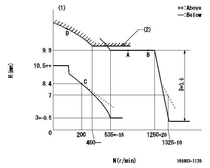
N:Pump speed
R:Rack position (mm)
(1)Beginning of damper spring operation: DL
(2)Set using excess fuel device for starting: SXL
----------
DL=8-0.2mm SXL=9.9+0.2mm
----------
----------
DL=8-0.2mm SXL=9.9+0.2mm
----------
0000000901
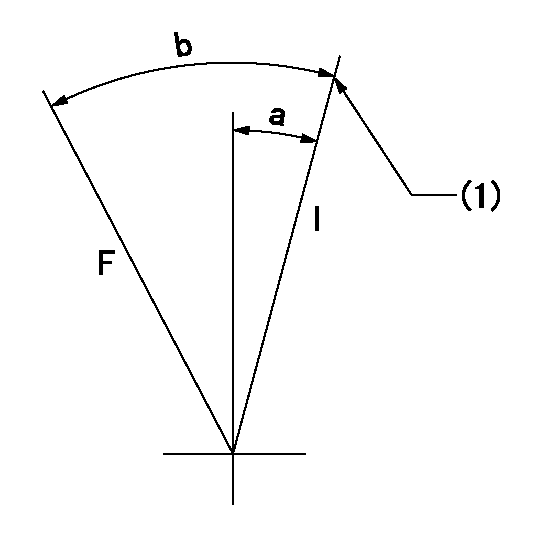
F:Full load
I:Idle
(1)Stopper bolt setting
----------
----------
a=5.5deg+-5deg b=25.5deg+-3deg
----------
----------
a=5.5deg+-5deg b=25.5deg+-3deg
0000001501 MICRO SWITCH
Adjustment of the micro-switch
Adjust the bolt to obtain the following lever position when the micro-switch is ON.
(1)Speed N1
(2)Rack position Ra
----------
N1=325+5r/min Ra=7.8mm
----------
----------
N1=325+5r/min Ra=7.8mm
----------
Information:
Do not operate or work on this product unless you have read and understood the instruction and warnings in the relevant Operation and Maintenance Manuals and relevant service literature. Failure to follow the instructions or heed the warnings could result in injury or death. Proper care is your responsibility.
New DEF sensor kits are available. The new sensor kit allows the DEF sensor to be repaired on DEF manifold assemblies.Note: If troubleshooting procedures indicate a replacement of the DEF manifold, do not replace the DEF Manifold. Repair the DEF Manifold using the DEF manifold sensor kit.Refer to Table 1 for the appropriate DEF sensor kit for the DEF manifold installed.
Table 1
DEF manifold Part Number Part Description Repair with DEF Sensor Kit
462-3219 11 inch (279mm) Manifold 593-0641
462-3610 13 inch (330mm) Manifold 593-0642
462-3232 18 inch (457mm) Manifold 593-0643
Illustration 1 g06508474New disassembly and assembly instructions are available. Refer to Disassembly and Assembly, Manifold (DEF Heater) - Disassemble and Disassembly and Assembly, Manifold (DEF Heater) - Assemble for the correct procedures.
Have questions with 101803-1170?
Group cross 101803-1170 ZEXEL
Mitsubishi
101803-1170
3126173023
INJECTION-PUMP ASSEMBLY
8DC7
8DC7