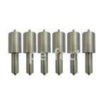
Information injection-pump assembly
BOSCH
F 019 Z20 050
f019z20050
ZEXEL
101701-9580
1017019580
NISSAN-DIESEL
16713NB002
16713nb002

Rating:
Service parts 101701-9580 INJECTION-PUMP ASSEMBLY:
1.
_
7.
COUPLING PLATE
8.
_
9.
_
11.
Nozzle and Holder
1660095013
12.
Open Pre:MPa(Kqf/cm2)
19.6{200}
15.
NOZZLE SET
Cross reference number
BOSCH
F 019 Z20 050
f019z20050
ZEXEL
101701-9580
1017019580
NISSAN-DIESEL
16713NB002
16713nb002
Zexel num
Bosch num
Firm num
Name
101701-9580
F 019 Z20 050
16713NB002 NISSAN-DIESEL
INJECTION-PUMP ASSEMBLY
NE6 K 14BE INJECTION PUMP ASSY PE6A PE
NE6 K 14BE INJECTION PUMP ASSY PE6A PE
Calibration Data:
Adjustment conditions
Test oil
1404 Test oil ISO4113 or {SAEJ967d}
1404 Test oil ISO4113 or {SAEJ967d}
Test oil temperature
degC
40
40
45
Nozzle and nozzle holder
105780-8140
Bosch type code
EF8511/9A
Nozzle
105780-0000
Bosch type code
DN12SD12T
Nozzle holder
105780-2080
Bosch type code
EF8511/9
Opening pressure
MPa
17.2
Opening pressure
kgf/cm2
175
Injection pipe
Outer diameter - inner diameter - length (mm) mm 6-2-600
Outer diameter - inner diameter - length (mm) mm 6-2-600
Overflow valve
131424-1520
Overflow valve opening pressure
kPa
157
123
191
Overflow valve opening pressure
kgf/cm2
1.6
1.25
1.95
Tester oil delivery pressure
kPa
157
157
157
Tester oil delivery pressure
kgf/cm2
1.6
1.6
1.6
Direction of rotation (viewed from drive side)
Right R
Right R
Injection timing adjustment
Direction of rotation (viewed from drive side)
Right R
Right R
Injection order
1-4-2-6-
3-5
Pre-stroke
mm
3
2.95
3.05
Beginning of injection position
Drive side NO.1
Drive side NO.1
Difference between angles 1
Cal 1-4 deg. 60 59.5 60.5
Cal 1-4 deg. 60 59.5 60.5
Difference between angles 2
Cyl.1-2 deg. 120 119.5 120.5
Cyl.1-2 deg. 120 119.5 120.5
Difference between angles 3
Cal 1-6 deg. 180 179.5 180.5
Cal 1-6 deg. 180 179.5 180.5
Difference between angles 4
Cal 1-3 deg. 240 239.5 240.5
Cal 1-3 deg. 240 239.5 240.5
Difference between angles 5
Cal 1-5 deg. 300 299.5 300.5
Cal 1-5 deg. 300 299.5 300.5
Injection quantity adjustment
Adjusting point
A
Rack position
8.8
Pump speed
r/min
1400
1400
1400
Average injection quantity
mm3/st.
79.4
78.4
80.4
Max. variation between cylinders
%
0
-3.5
3.5
Basic
*
Fixing the lever
*
Injection quantity adjustment_02
Adjusting point
B
Rack position
9.2
Pump speed
r/min
600
600
600
Average injection quantity
mm3/st.
68.3
66.3
70.3
Max. variation between cylinders
%
0
-5
5
Fixing the lever
*
Injection quantity adjustment_03
Adjusting point
C
Rack position
7.2+-0.5
Pump speed
r/min
285
285
285
Average injection quantity
mm3/st.
9
7.2
10.8
Max. variation between cylinders
%
0
-10
10
Fixing the rack
*
Injection quantity adjustment_04
Adjusting point
D
Rack position
13.2+-0.
5
Pump speed
r/min
150
150
150
Average injection quantity
mm3/st.
115
115
Fixing the lever
*
Remarks
After startup boost setting
After startup boost setting
Timer adjustment
Pump speed
r/min
550--
Advance angle
deg.
0
0
0
Remarks
Start
Start
Timer adjustment_02
Pump speed
r/min
500
Advance angle
deg.
0.5
Timer adjustment_03
Pump speed
r/min
800
Remarks
Measure the actual advance angle.
Measure the actual advance angle.
Timer adjustment_04
Pump speed
r/min
1200
Advance angle
deg.
4
3.5
4.5
Remarks
Finish
Finish
Test data Ex:
Governor adjustment
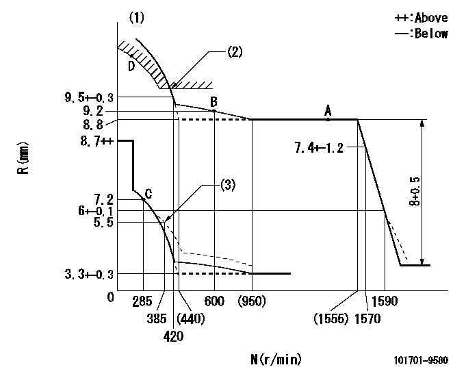
N:Pump speed
R:Rack position (mm)
(1)Tolerance for racks not indicated: +-0.05mm.
(2)Excess fuel setting for starting: SXL (N = N1)
(3)Damper spring setting
----------
SXL=10+0.2mm N1=380r/min
----------
----------
SXL=10+0.2mm N1=380r/min
----------
Speed control lever angle
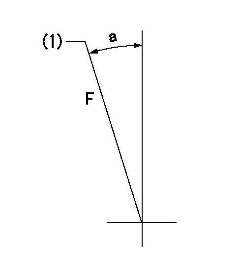
F:Full speed
(1)Stopper bolt setting
----------
----------
a=(13deg)+-5deg
----------
----------
a=(13deg)+-5deg
0000000901
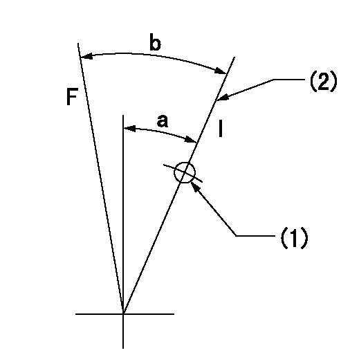
F:Full load
I:Idle
(1)Use the hole at R = aa
(2)Stopper bolt setting
----------
aa=65mm
----------
a=16.5deg+-5deg b=20.5deg+-3deg
----------
aa=65mm
----------
a=16.5deg+-5deg b=20.5deg+-3deg
Stop lever angle
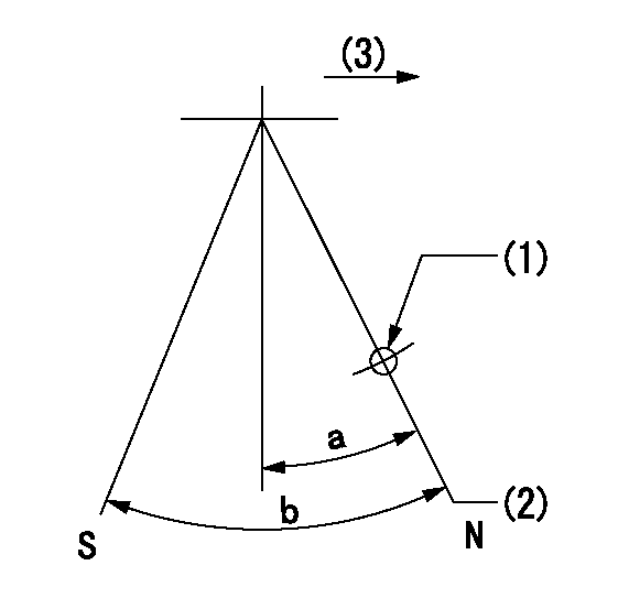
N:Pump normal
S:Stop the pump.
(1)Use the pin at R = aa
(2)Normal
(3)Drive side
----------
aa=20mm
----------
a=40deg+-5deg b=71deg+-5deg
----------
aa=20mm
----------
a=40deg+-5deg b=71deg+-5deg
Timing setting

(1)Pump vertical direction
(2)Coupling's key groove position at No 1 cylinder's beginning of injection
(3)-
(4)-
----------
----------
a=(30deg)
----------
----------
a=(30deg)
Information:
If equipped with an air inlet heater (AIH) for cold weather starting, do not use types of starting aids such as ether. Such use could result in an explosion and injury.
When starting the engine with ether, follow these starting procedure instructions carefully. Use ether sparingly and spray it ONLY WHILE CRANKING THE ENGINE. Excessive ether use can cause piston and ring damage. Ether should be used only for cold weather starting.
Table 1
Medium and Heavy-Duty On-Highway Engines (1)
Cold Weather Recommendations
Starting Aids
Expected Coldest Temperature Ether Injection (2)
OR
Air Inlet Heater Cylinder Block Coolant Heater Larger Battery
Larger Alternator
Above
−7 °C (19 °F) Available Available Available
−7 °C (19 °F) to
−18 °C (0 °F) Available Available Available
−18 °C (0 °F) to
−28 °C (−18 °F) Recommended Required Recommended
−28 °C (−18 °F) to
−40 °C (−40 °F) Recommended Required Required
Less than
−40 °C (−40 °F) Required Required Required
( 1 ) Options may not be available for all models.
( 2 ) If the engine is equipped with an air inlet heater (AIH) for cold weather starting, do not use types of starting aids such as ether. Such use could result in an explosion and injury.
Table 2
Medium and Heavy-Duty On-Highway Engines (1)
Cold Weather Recommendations
Improvements for Engine Warm-Up
Improvements for Idle Temperature
Expected Coldest Temperature Hand Throttles Winter Fronts
Shutters Air Cleaners
Located Under the Hood On/Off
Fan Drives BrakeSavers
Exhaust Restrictors
Above
−7 °C (19 °F) Available Available Available Available Available
−7 °C (19 °F) to
−18 °C (0 °F) Available Recommended Recommended Recommended Available
−18 °C (0 °F) to
−28 °C (−18 °F) Recommended Required Recommended Required Recommended
−28 °C (−18 °F) to
−40 °C (−40 °F) Required Required Recommended Required Recommended
Less than
−40 °C (−40 °F) Required Required Recommended Required Required
( 1 ) Options may not be available for all models.
Have questions with 101701-9580?
Group cross 101701-9580 ZEXEL
Nissan-Diesel
101701-9580
F 019 Z20 050
16713NB002
INJECTION-PUMP ASSEMBLY
NE6
NE6
