Information injection-pump assembly
BOSCH
9 400 611 450
9400611450
ZEXEL
101701-9270
1017019270
Rating:
Service parts 101701-9270 INJECTION-PUMP ASSEMBLY:
1.
_
7.
COUPLING PLATE
8.
_
9.
_
11.
Nozzle and Holder
16600-Z6008
12.
Open Pre:MPa(Kqf/cm2)
14.7{150}/17.7{180}
14.
NOZZLE
Cross reference number
BOSCH
9 400 611 450
9400611450
ZEXEL
101701-9270
1017019270
Zexel num
Bosch num
Firm num
Name
Calibration Data:
Adjustment conditions
Test oil
1404 Test oil ISO4113 or {SAEJ967d}
1404 Test oil ISO4113 or {SAEJ967d}
Test oil temperature
degC
40
40
45
Nozzle and nozzle holder
105780-8310
Nozzle
105780-0120
Bosch type code
1 688 901 990
Nozzle holder
105780-2240
Opening pressure
MPa
18
Opening pressure
kgf/cm2
184
Injection pipe
Outer diameter - inner diameter - length (mm) mm 6-2-600
Outer diameter - inner diameter - length (mm) mm 6-2-600
Overflow valve
134424-4120
Overflow valve opening pressure
kPa
255
221
289
Overflow valve opening pressure
kgf/cm2
2.6
2.25
2.95
Tester oil delivery pressure
kPa
255
255
255
Tester oil delivery pressure
kgf/cm2
2.6
2.6
2.6
Direction of rotation (viewed from drive side)
Left L
Left L
Injection timing adjustment
Direction of rotation (viewed from drive side)
Left L
Left L
Injection order
1-4-2-6-
3-5
Pre-stroke
mm
3.5
3.47
3.53
Beginning of injection position
Governor side NO.1
Governor side NO.1
Difference between angles 1
Cal 1-4 deg. 60 59.75 60.25
Cal 1-4 deg. 60 59.75 60.25
Difference between angles 2
Cyl.1-2 deg. 120 119.75 120.25
Cyl.1-2 deg. 120 119.75 120.25
Difference between angles 3
Cal 1-6 deg. 180 179.75 180.25
Cal 1-6 deg. 180 179.75 180.25
Difference between angles 4
Cal 1-3 deg. 240 239.75 240.25
Cal 1-3 deg. 240 239.75 240.25
Difference between angles 5
Cal 1-5 deg. 300 299.75 300.25
Cal 1-5 deg. 300 299.75 300.25
Injection quantity adjustment
Adjusting point
-
Rack position
12.6
Pump speed
r/min
700
700
700
Average injection quantity
mm3/st.
56
54
58
Max. variation between cylinders
%
0
-3.5
3.5
Basic
*
Fixing the rack
*
Standard for adjustment of the maximum variation between cylinders
*
Injection quantity adjustment_02
Adjusting point
Z
Rack position
9.7+-0.5
Pump speed
r/min
325
325
325
Average injection quantity
mm3/st.
13
12
14
Max. variation between cylinders
%
0
-10
10
Fixing the rack
*
Standard for adjustment of the maximum variation between cylinders
*
Injection quantity adjustment_03
Adjusting point
A
Rack position
R1(12.6)
Pump speed
r/min
700
700
700
Average injection quantity
mm3/st.
56
55
57
Basic
*
Fixing the lever
*
Injection quantity adjustment_04
Adjusting point
B
Rack position
R1+1.3
Pump speed
r/min
1300
1300
1300
Average injection quantity
mm3/st.
61.5
57.5
65.5
Fixing the lever
*
Timer adjustment
Pump speed
r/min
(N1+50)-
-
Advance angle
deg.
0
0
0
Remarks
Start
Start
Timer adjustment_02
Pump speed
r/min
N1
Advance angle
deg.
0.3
Remarks
Measure the actual speed.
Measure the actual speed.
Timer adjustment_03
Pump speed
r/min
-
Advance angle
deg.
4
3.7
4.3
Remarks
Measure the actual speed, stop
Measure the actual speed, stop
Test data Ex:
Governor adjustment
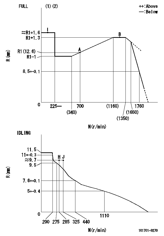
N:Pump speed
R:Rack position (mm)
(1)Torque cam stamping: T1
(2)Tolerance for racks not indicated: +-0.05mm.
----------
T1=N87
----------
----------
T1=N87
----------
Speed control lever angle

F:Full speed
I:Idle
(1)Use the hole at R = aa
(2)Stopper bolt set position 'H'
----------
aa=38mm
----------
a=7deg+-5deg b=41deg+-3deg
----------
aa=38mm
----------
a=7deg+-5deg b=41deg+-3deg
Stop lever angle
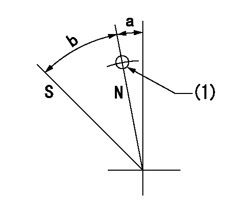
N:Pump normal
S:Stop the pump.
(1)Use the pin at R = aa
----------
aa=42mm
----------
a=5deg+-5deg b=40deg+-5deg
----------
aa=42mm
----------
a=5deg+-5deg b=40deg+-5deg
0000001501 RACK SENSOR
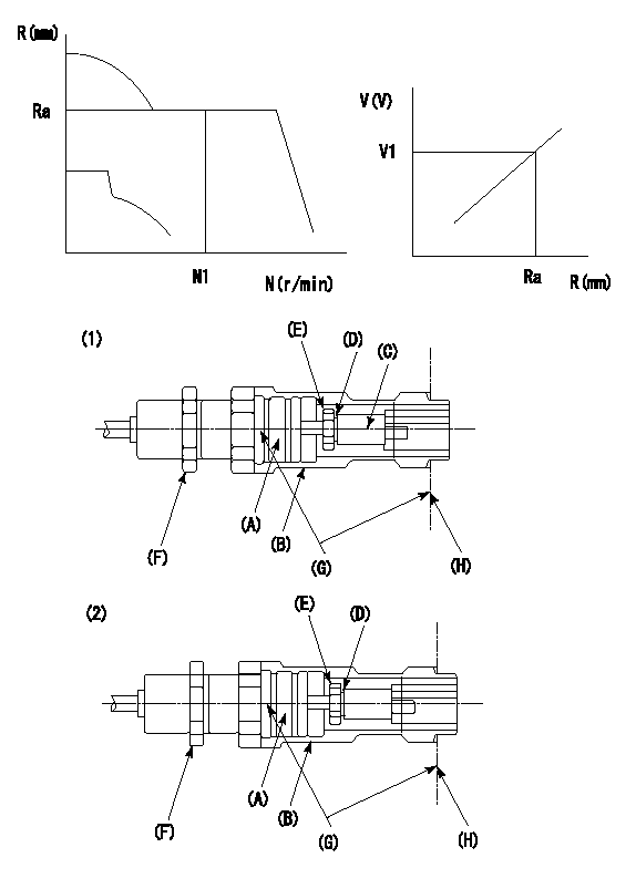
G:Red paint
H:Pump end face
P/N: part number of suitable shim
(1)Threaded type rack block
(2)Welded type rack block
Rack sensor adjustment
1. Threaded type rack sensor (-5*20, P type, no TICS rack limit).
(1)Screw in the bobbin (A) until it contacts the joint (B).
(2)Fix the pump lever.
(3)At speed N1 and rack position Ra, adjust the amount that the bobbin is screwed in so that the amp's output voltage is V1.
(4)Fix using the nut (F).
(5)Affix the caution plate to the upper part of the joint (B).
(6)Apply (G) at two places.
Connecting part between the joint (B) and the nut (F)
Connecting part between the end surface of the pump (H) and the joint (B)
2. Range for screw-in adjustment between the bobbin (A) and the joint (B) is 9 threads.
Screw in to the end from (the position where the bobbin (A) is rotated 9 turns).
Speed N1, rack position Ra, output voltage V1, rack sensor supply voltage 5+-0.01 (V)
----------
Ra=R1(12.6)mm N1=700r/min V1=2.6+-0.01V
----------
----------
Ra=R1(12.6)mm N1=700r/min V1=2.6+-0.01V
----------
Timing setting

(1)Pump vertical direction
(2)Coupling's key groove position at No 1 cylinder's beginning of injection
(3)-
(4)-
----------
----------
a=(10deg)
----------
----------
a=(10deg)
Information:
Remove the single tie bolt (6) that is located in the top left corner of the pump by using Tooling (B). Refer to Illustration 7. Only remove the single tie bolt (6). Removing more bolts will result in damage to the pump.
Illustration 2 g01132938
(1) HEUI pump (2) Fuel transfer pump (4) Drive gear (5) 227-5904 O-Ring Seal (6) Tie Bolt (7) Bolts for the fuel transfer pump (8) Tie Bolts (9) Location for service bolt (12) 185-3241 O-Ring Seal
Replace tie bolt (6) with the temporary service bolt (9) that is provided in the service kit.Note: The service bolt that is provided in the kit has an undersized bolt head. The service bolt prevents the body of the HEUI pump from separating during service. Do not remove the service bolt until the fuel transfer pump has been completely reinstalled.
Tighten the service bolt (9) to 10 N m (7.4 lb ft) by using Tooling (C) .Note: Do not place an excessive torque on the service bolt. The aluminum housing of the pump could be damaged.
After installing the service bolt (9) in the top left location, remove the three bolts (7) that fasten the fuel transfer pump to the HEUI pump by using Tooling (A) .
Proceed by removing the remaining three tie bolts (8) by using Tooling (B) .
Separate the fuel transfer pump from the HEUI pump. Refer to Illustration 3.
Illustration 3 g01132944
(1) HEUI pump (2) Fuel transfer pump (9) Service bolt (10) Seals (11) SealInstalling the Fuel Transfer Pump onto the HEUI Pump
Install the two new 239-2402 Seals (10) on the back face of the HEUI pump (1). Refer to Illustration 4.
Illustration 4 g01077898
(1) HEUI pump (10) 239-2402 Seals
Install a new 179-8128 Seal (11) on the fuel transfer pump (2). Refer to Illustration 5. Use 1U-6396 O-Ring Assembly Compound in order to hold the seal in place during assembly. Ensure that the seal is completely seated.
Illustration 5 g01132957
(2) Fuel transfer pump (11) 179-8128 Seal
Do not remove the service bolt. Position the fuel transfer pump on the HEUI pump. Be sure to properly align the drive tang on the fuel transfer pump with the drive slot on the HEUI pump.Note: Align the drive tang of the fuel transfer pump so that the flat end is vertical. Refer to Illustration 5. Align the drive slot in the HEUI pump to a similar vertical orientation by using a flat head screwdriver. Refer to Illustration 6.
Illustration 6 g01132969
Note: Once the fuel transfer pump has been placed onto the HEUI pump, ensure that the face of the fuel transfer pump is flush with the face of the HEUI pump. If the pump faces are not flush, verify the alignment of the drive tang.
Install the three mounting bolts (7) for the fuel transfer pump (2). Tighten