Information injection-pump assembly
BOSCH
F 01G 09U 074
f01g09u074
ZEXEL
101701-9240
1017019240
NISSAN-DIESEL
16714Z6011
16714z6011
Rating:
Include in #1:
106871-2022
as _
Cross reference number
BOSCH
F 01G 09U 074
f01g09u074
ZEXEL
101701-9240
1017019240
NISSAN-DIESEL
16714Z6011
16714z6011
Zexel num
Bosch num
Firm num
Name
Calibration Data:
Adjustment conditions
Test oil
1404 Test oil ISO4113 or {SAEJ967d}
1404 Test oil ISO4113 or {SAEJ967d}
Test oil temperature
degC
40
40
45
Nozzle and nozzle holder
105780-8310
Nozzle
105780-0120
Bosch type code
1 688 901 990
Nozzle holder
105780-2240
Opening pressure
MPa
18
Opening pressure
kgf/cm2
184
Injection pipe
Outer diameter - inner diameter - length (mm) mm 6-2-600
Outer diameter - inner diameter - length (mm) mm 6-2-600
Overflow valve
134424-4120
Overflow valve opening pressure
kPa
255
221
289
Overflow valve opening pressure
kgf/cm2
2.6
2.25
2.95
Tester oil delivery pressure
kPa
255
255
255
Tester oil delivery pressure
kgf/cm2
2.6
2.6
2.6
Direction of rotation (viewed from drive side)
Left L
Left L
Injection timing adjustment
Direction of rotation (viewed from drive side)
Left L
Left L
Injection order
1-4-2-6-
3-5
Pre-stroke
mm
3.5
3.47
3.53
Beginning of injection position
Governor side NO.1
Governor side NO.1
Difference between angles 1
Cal 1-4 deg. 60 59.75 60.25
Cal 1-4 deg. 60 59.75 60.25
Difference between angles 2
Cyl.1-2 deg. 120 119.75 120.25
Cyl.1-2 deg. 120 119.75 120.25
Difference between angles 3
Cal 1-6 deg. 180 179.75 180.25
Cal 1-6 deg. 180 179.75 180.25
Difference between angles 4
Cal 1-3 deg. 240 239.75 240.25
Cal 1-3 deg. 240 239.75 240.25
Difference between angles 5
Cal 1-5 deg. 300 299.75 300.25
Cal 1-5 deg. 300 299.75 300.25
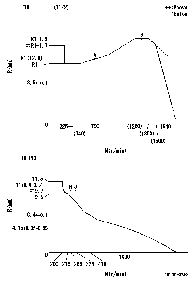
Injection quantity adjustment
Adjusting point
-
Rack position
12.8
Pump speed
r/min
700
700
700
Average injection quantity
mm3/st.
57.5
55.5
59.5
Max. variation between cylinders
%
0
-3.5
3.5
Basic
*
Fixing the rack
*
Standard for adjustment of the maximum variation between cylinders
*
Injection quantity adjustment_02
Adjusting point
Z
Rack position
9.7+-0.5
Pump speed
r/min
325
325
325
Average injection quantity
mm3/st.
13
12
14
Max. variation between cylinders
%
0
-10
10
Fixing the rack
*
Standard for adjustment of the maximum variation between cylinders
*
Injection quantity adjustment_03
Adjusting point
A
Rack position
R1(12.8)
Pump speed
r/min
700
700
700
Average injection quantity
mm3/st.
57.5
56.5
58.5
Basic
*
Fixing the lever
*
Injection quantity adjustment_04
Adjusting point
B
Rack position
R1+1.9
Pump speed
r/min
1300
1300
1300
Average injection quantity
mm3/st.
66.5
62.5
70.5
Fixing the lever
*
Timer adjustment
Pump speed
r/min
900--
Advance angle
deg.
0
0
0
Remarks
Start
Start
Timer adjustment_02
Pump speed
r/min
850
Advance angle
deg.
0.3
Timer adjustment_03
Pump speed
r/min
1300
Advance angle
deg.
4
3.7
4.3
Remarks
Finish
Finish
Test data Ex:
Governor adjustment
N:Pump speed
R:Rack position (mm)
(1)Torque cam stamping: T1
(2)Tolerance for racks not indicated: +-0.05mm.
----------
T1=N78
----------
----------
T1=N78
----------
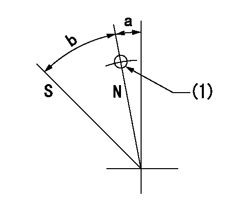
Speed control lever angle

F:Full speed
I:Idle
(1)Use the hole at R = aa
(2)Stopper bolt set position 'H'
----------
aa=36mm
----------
a=8deg+-5deg b=(43deg)+-3deg
----------
aa=36mm
----------
a=8deg+-5deg b=(43deg)+-3deg
Stop lever angle
N:Pump normal
S:Stop the pump.
(1)Use the pin at R = aa
----------
aa=42mm
----------
a=5deg+-5deg b=40deg+-5deg
----------
aa=42mm
----------
a=5deg+-5deg b=40deg+-5deg
0000001501 RACK SENSOR
G:Red paint
H:Pump end face
P/N: part number of suitable shim
(1)Threaded type rack block
(2)Welded type rack block
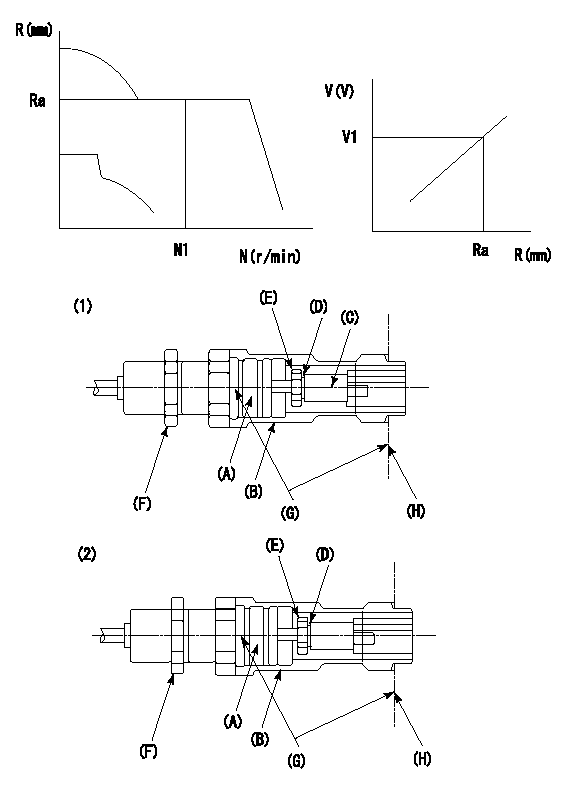
Rack sensor adjustment
1. Threaded type rack sensor (-5*20, P type, no TICS rack limit).
(1)Screw in the bobbin (A) until it contacts the joint (B).
(2)Fix the pump lever.
(3)At speed N1 and rack position Ra, adjust the amount that the bobbin is screwed in so that the amp's output voltage is V1.
(4)Fix using the nut (F).
(5)Affix the caution plate to the upper part of the joint (B).
(6)Apply (G) at two places.
Connecting part between the joint (B) and the nut (F)
Connecting part between the end surface of the pump (H) and the joint (B)
2. Range for screw-in adjustment between the bobbin (A) and the joint (B) is 9 threads.
Screw in to the end from (the position where the bobbin (A) is rotated 9 turns).
Speed N1, rack position Ra, output voltage V1, rack sensor supply voltage 5+-0.01 (V)
----------
Ra=R1(12.8)+1.9mm N1=1300r/min V1=3+-0.01V
----------
----------
Ra=R1(12.8)+1.9mm N1=1300r/min V1=3+-0.01V
----------
Timing setting

(1)Pump vertical direction
(2)Position of timer's threaded hole at No 1 cylinder's beginning of injection
(3)-
(4)-
----------
----------
a=(80deg)
----------
----------
a=(80deg)
Information:
Introduction
The problem that is identified below does not have a known permanent solution. Until a permanent solution is known, use the solution that is identified below.Problem
An industry-wide issue has arisen with a specific type of deposit that forms in modern fuel injection systems and has a negative effect on operation.The C175 fuel system operates under higher pressures and temperatures than previous injection systems. Clearances between precision moving parts can be minute, typically less than 5 microns.A soapy type of deposit has been found in some C175 fuel injection systems. The formation of the deposits is being investigated by Caterpillar, along with the fuel industry and the petroleum industry.The cause of the deposits is complex, involving these kinds of variables:
Temperature
Pressure
Fuel chemistry
Water and contaminants in the fuelThe following symptoms are associated with the soapy deposits in the fuel injectors:
A loss of power
Excessive variations in exhaust temperature
Rough running
Hard starting, especially after allowing an engine to cool down before restarting
Stuck injectorsSevere deposits cause the injector to stick in one position, resulting in a cylinder that does not fire.To verify the presence of the deposits, the injector from a cold cylinder must be returned to Caterpillar.Solution
If the above symptoms are diagnosed or if the deposits are confirmed, use 343-6210 Cleaner (FUEL) to remove the deposits.The 343-6210 Cleaner (FUEL) is the only fuel system cleaner that has been tested and approved by Cat for use in Cat diesel engines.For sites that are more susceptible to injector deposits, maintain a supply of 343-6210 Cleaner (FUEL) in order to address the problem quickly.For more information, refer to the "Cat Diesel Fuel System Cleaner" topic in Operation and Maintenance Manual, SEBU6250, "Caterpillar Machine Fluids Recommendations" or in Operation and Maintenance Manual, SEBU6251, "Cat Commercial Diesel Engine Fluids Recommendations".Note: Depending on the amounts of deposits, the fuel filter may plug after initial use of the cleaner due to removal of the deposits. The frequency of the plugging will decrease as the fuel system returns to a condition that is clean and stable.Perform the following recommendations in order to reduce the potential for the formation of injector deposits:
Prior to filling the engine fuel tank with fuel from a storage tank, filter the fuel through an absolute filter of 4 µm.
Use filters of 4 µm filtration on the breathers of fuel storage tanks. In dusty environments, use a filter of 4 µm on the breather of the engine fuel tank.
Regularly monitor bulk fuel in order to ensure that concentrations of calcium, sodium, zinc, and magnesium are less than 1 ppm.
Caterpillar does not generally recommend the use of aftermarket fuel additives. If an aftermarket fuel additive is considered to be necessary, use the additive with caution. Follow the guidelines in the "Aftermarket Fuel Additives" topic in Operation and Maintenance Manual, SEBU6250, "Caterpillar Machine Fluids Recommendations" or in Operation and Maintenance Manual, SEBU6251, "Cat Commercial Diesel Engine Fluids Recommendations".
Make sure that the