Information injection-pump assembly
BOSCH
9 400 616 177
9400616177
ZEXEL
101697-9120
1016979120
NISSAN-DIESEL
16714Z5616
16714z5616
Rating:
Include in #1:
106871-7260
as _
Cross reference number
BOSCH
9 400 616 177
9400616177
ZEXEL
101697-9120
1016979120
NISSAN-DIESEL
16714Z5616
16714z5616
Zexel num
Bosch num
Firm num
Name
101697-9120
9 400 616 177
16714Z5616 NISSAN-DIESEL
INJECTION-PUMP ASSEMBLY
FE6T K
FE6T K
Calibration Data:
Adjustment conditions
Test oil
1404 Test oil ISO4113 or {SAEJ967d}
1404 Test oil ISO4113 or {SAEJ967d}
Test oil temperature
degC
40
40
45
Nozzle and nozzle holder
105780-8140
Bosch type code
EF8511/9A
Nozzle
105780-0000
Bosch type code
DN12SD12T
Nozzle holder
105780-2080
Bosch type code
EF8511/9
Opening pressure
MPa
17.2
Opening pressure
kgf/cm2
175
Injection pipe
Outer diameter - inner diameter - length (mm) mm 6-2-600
Outer diameter - inner diameter - length (mm) mm 6-2-600
Overflow valve
134424-1520
Overflow valve opening pressure
kPa
162
147
177
Overflow valve opening pressure
kgf/cm2
1.65
1.5
1.8
Tester oil delivery pressure
kPa
157
157
157
Tester oil delivery pressure
kgf/cm2
1.6
1.6
1.6
Direction of rotation (viewed from drive side)
Right R
Right R
Injection timing adjustment
Direction of rotation (viewed from drive side)
Right R
Right R
Injection order
1-4-2-6-
3-5
Pre-stroke
mm
3.9
3.85
3.95
Beginning of injection position
Drive side NO.1
Drive side NO.1
Difference between angles 1
Cal 1-4 deg. 60 59.5 60.5
Cal 1-4 deg. 60 59.5 60.5
Difference between angles 2
Cyl.1-2 deg. 120 119.5 120.5
Cyl.1-2 deg. 120 119.5 120.5
Difference between angles 3
Cal 1-6 deg. 180 179.5 180.5
Cal 1-6 deg. 180 179.5 180.5
Difference between angles 4
Cal 1-3 deg. 240 239.5 240.5
Cal 1-3 deg. 240 239.5 240.5
Difference between angles 5
Cal 1-5 deg. 300 299.5 300.5
Cal 1-5 deg. 300 299.5 300.5
Injection quantity adjustment
Adjusting point
-
Rack position
13.6
Pump speed
r/min
700
700
700
Average injection quantity
mm3/st.
92.5
90.5
94.5
Max. variation between cylinders
%
0
-3.5
3.5
Basic
*
Fixing the rack
*
Standard for adjustment of the maximum variation between cylinders
*
Injection quantity adjustment_02
Adjusting point
H
Rack position
9.7+-0.5
Pump speed
r/min
275
275
275
Average injection quantity
mm3/st.
17
15.2
18.8
Max. variation between cylinders
%
0
-10
10
Fixing the rack
*
Standard for adjustment of the maximum variation between cylinders
*
Injection quantity adjustment_03
Adjusting point
A
Rack position
R1(13.6)
Pump speed
r/min
700
700
700
Average injection quantity
mm3/st.
92.5
91.5
93.5
Basic
*
Fixing the lever
*
Boost pressure
kPa
40
40
Boost pressure
mmHg
300
300
Injection quantity adjustment_04
Adjusting point
B
Rack position
(R1+0.3)
+0.05-0.
15
Pump speed
r/min
1400
1400
1400
Average injection quantity
mm3/st.
99.5
96.3
102.7
Fixing the lever
*
Boost pressure
kPa
40
40
Boost pressure
mmHg
300
300
Injection quantity adjustment_05
Adjusting point
C
Rack position
R2(R1-0.
2)
Pump speed
r/min
420
420
420
Average injection quantity
mm3/st.
80
76.8
83.2
Fixing the lever
*
Boost pressure
kPa
40
40
Boost pressure
mmHg
300
300
Injection quantity adjustment_06
Adjusting point
D
Rack position
R2-1.8
Pump speed
r/min
420
420
420
Average injection quantity
mm3/st.
46
44
48
Fixing the lever
*
Boost pressure
kPa
0
0
0
Boost pressure
mmHg
0
0
0
Injection quantity adjustment_07
Adjusting point
I
Rack position
-
Pump speed
r/min
150
150
150
Average injection quantity
mm3/st.
105
105
125
Fixing the lever
*
Boost pressure
kPa
0
0
0
Boost pressure
mmHg
0
0
0
Rack limit
*
Boost compensator adjustment
Pump speed
r/min
420
420
420
Rack position
R2-1.8
Boost pressure
kPa
12
10.7
13.3
Boost pressure
mmHg
90
80
100
Boost compensator adjustment_02
Pump speed
r/min
420
420
420
Rack position
R2(R1-0.
2)
Boost pressure
kPa
26.7
26.7
26.7
Boost pressure
mmHg
200
200
200
Timer adjustment
Pump speed
r/min
1170--
Advance angle
deg.
0
0
0
Remarks
Start
Start
Timer adjustment_02
Pump speed
r/min
1120
Advance angle
deg.
0.5
Timer adjustment_03
Pump speed
r/min
1400
Advance angle
deg.
3
2.5
3.5
Remarks
Finish
Finish
Test data Ex:
Governor adjustment
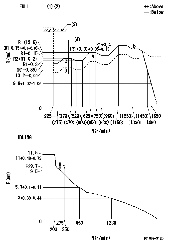
N:Pump speed
R:Rack position (mm)
(1)Torque cam stamping: T1
(2)Tolerance for racks not indicated: +-0.05mm.
(3)RACK LIMIT
(4)Boost compensator stroke: BCL
----------
T1=M68 BCL=1.8+-0.1mm
----------
----------
T1=M68 BCL=1.8+-0.1mm
----------
Speed control lever angle

F:Full speed
I:Idle
(1)Use the hole at R = aa
(2)Stopper bolt set position 'H'
----------
aa=36mm
----------
a=26deg+-5deg b=39deg+-3deg
----------
aa=36mm
----------
a=26deg+-5deg b=39deg+-3deg
Stop lever angle
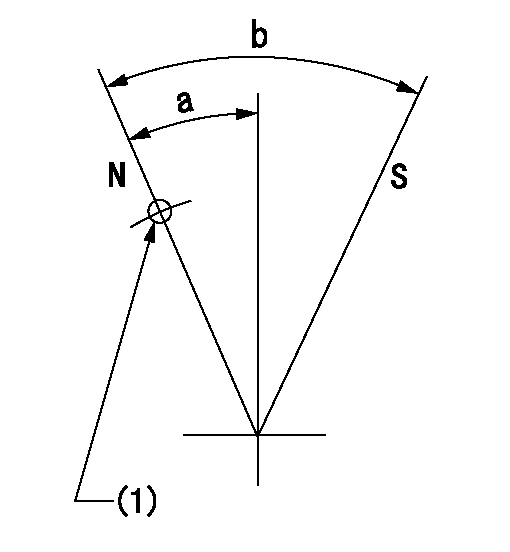
N:Pump normal
S:Stop the pump.
(1)Use the pin at R = aa
----------
aa=42mm
----------
a=27deg+-5deg b=40deg+-5deg
----------
aa=42mm
----------
a=27deg+-5deg b=40deg+-5deg
Timing setting

(1)Pump vertical direction
(2)Coupling's key groove position at No 1 cylinder's beginning of injection
(3)-
(4)-
----------
----------
a=(30deg)
----------
----------
a=(30deg)
Information:
Introduction
The following Special Instruction must be used to package a DPF for a core return.
Wear goggles, gloves, protective clothing, and a National Institute for Occupational Safety and Health (NIOSH) approved P95 or N95 half-face respirator when handling a used Diesel Particulate Filter or Catalytic Converter Muffler. Failure to do so could result in personal injury.
Note: Whenever the filter is replaced the engine ash model must be reset. Refer to the section below for information on how to reset the ash model.Reset the Engine Ash Model
The engine ash model must be reset whenever the filter is cleaned or replaced. Reseting the ash model places the DPF volume back to the "Clean State". The resetting will allow the regeneration of the DPF to function properly.
Use Cat ET to access the configuration parameters. Select "Service" from the top menu then select "Service Procedures" then select "DPF Ash Service" from the menu in the service tool.
Choose the correct replacement type of diesel particulate filter in the menu that appears. The types of replacements for the diesel particulate filter are the following:
"Field cleaned" A DPF that has been cleaned and reapplied.
"New" A new DPF replacement.
"Remanufactured" A remanufactured DPF replacement.
Once the reset is completed, a log of the reset is captured and visible as a new row of information in the "DPF Ash Service" screen. Resetting the engine ash model does not reset the soot level.
Perform a "Manual DPF Regeneration" with Cat® ET to reset the soot levelPackaging Instructions
Note: The replacement DPF will be packaged with a bag and zip-tie that are used to repackage the DPF that has been removed.
Place the DPF being returned in the enclosed bag and seal the bag with the enclosed zip-tie.
Place the enclosed warning label on the outside of the bag.
Place half of the foam insert on the bottom of the original shipping box with the cut out in the insert facing up.
Place the DPF into the box fitting the DPF into the cut out in the insert.
Place the second half of the foam insert on to of the DPF with the cut out in the insert facing down onto the DPF.
Seal the box with packing tape.Note: If the package weighs over 16 kg (35 lb), additional tape or banding might be required.
Label the package for return shipment.
Have questions with 101697-9120?
Group cross 101697-9120 ZEXEL
Nissan-Diesel
101697-9120
9 400 616 177
16714Z5616
INJECTION-PUMP ASSEMBLY
FE6T
FE6T