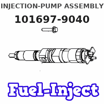
Information injection-pump assembly
BOSCH
9 400 611 613
9400611613
ZEXEL
101697-9040
1016979040

Rating:
Service parts 101697-9040 INJECTION-PUMP ASSEMBLY:
1.
_
7.
COUPLING PLATE
8.
_
9.
_
11.
Nozzle and Holder
16600-Z5607
12.
Open Pre:MPa(Kqf/cm2)
19.6{200}
15.
NOZZLE SET
Cross reference number
Zexel num
Bosch num
Firm num
Name
Information:
Test Procedure
System Operation
A thermocouple is a temperature sensor. The thermocouple consists of two different metals. The metals are joined together at one end. A small voltage is produced when the junction is heated. The change in voltage is interpreted by an electronic device in order to determine a change in temperature. The MMS uses K type thermocouples. The K type thermocouples have ranges from -200 °C (-328 °F)to 1260 °C (2300 °F). This temperature range corresponds to a voltage range of negative 5.9 mV to 51.0 mV.The signal is used in order to trigger alarms and the signal is used in order to display the parameter.
Illustration 1 g00563634
Diagram of the thermocouple
Illustration 2 g00563637
Schematic of the thermocoupleFunctional Test
Check the electrical connectors and check the wiring.
Bodily contact with electrical potential can cause bodily injury or death.To avoid the possibility of injury or death, ensure that the main power supply has been disconnected before performing any maintenance or removing any modules.
Disconnect the power supply.
Check the electrical connectors and check the wiring for damage or bad connections.
Verify that all modules are properly seated.
Verify the status of the LED on the SLC 5/04.The results of the preceding procedure are in the following list:
All of the components are fully installed. All of the components are free of corrosion. All of the components are free of damage. All of the modules are properly seated. Stop.
The components are not fully installed. The components are not free of corrosion. The components are damaged. All of the modules are not properly seated. Repair the component. Verify that the repair resolves the problem. STOP.

