Information injection-pump assembly
BOSCH
9 400 616 166
9400616166
ZEXEL
101696-9990
1016969990
NISSAN-DIESEL
16713Z6871
16713z6871
Rating:
Include in #1:
106871-7040
as _
Cross reference number
BOSCH
9 400 616 166
9400616166
ZEXEL
101696-9990
1016969990
NISSAN-DIESEL
16713Z6871
16713z6871
Zexel num
Bosch num
Firm num
Name
101696-9990
9 400 616 166
16713Z6871 NISSAN-DIESEL
INJECTION-PUMP ASSEMBLY
FE6T K
FE6T K
Calibration Data:
Adjustment conditions
Test oil
1404 Test oil ISO4113 or {SAEJ967d}
1404 Test oil ISO4113 or {SAEJ967d}
Test oil temperature
degC
40
40
45
Nozzle and nozzle holder
105780-8140
Bosch type code
EF8511/9A
Nozzle
105780-0000
Bosch type code
DN12SD12T
Nozzle holder
105780-2080
Bosch type code
EF8511/9
Opening pressure
MPa
17.2
Opening pressure
kgf/cm2
175
Injection pipe
Outer diameter - inner diameter - length (mm) mm 6-2-600
Outer diameter - inner diameter - length (mm) mm 6-2-600
Overflow valve
134424-1520
Overflow valve opening pressure
kPa
162
147
177
Overflow valve opening pressure
kgf/cm2
1.65
1.5
1.8
Tester oil delivery pressure
kPa
157
157
157
Tester oil delivery pressure
kgf/cm2
1.6
1.6
1.6
Direction of rotation (viewed from drive side)
Right R
Right R
Injection timing adjustment
Direction of rotation (viewed from drive side)
Right R
Right R
Injection order
1-4-2-6-
3-5
Pre-stroke
mm
3.9
3.85
3.95
Beginning of injection position
Drive side NO.1
Drive side NO.1
Difference between angles 1
Cal 1-4 deg. 60 59.5 60.5
Cal 1-4 deg. 60 59.5 60.5
Difference between angles 2
Cyl.1-2 deg. 120 119.5 120.5
Cyl.1-2 deg. 120 119.5 120.5
Difference between angles 3
Cal 1-6 deg. 180 179.5 180.5
Cal 1-6 deg. 180 179.5 180.5
Difference between angles 4
Cal 1-3 deg. 240 239.5 240.5
Cal 1-3 deg. 240 239.5 240.5
Difference between angles 5
Cal 1-5 deg. 300 299.5 300.5
Cal 1-5 deg. 300 299.5 300.5
Injection quantity adjustment
Adjusting point
-
Rack position
13.6
Pump speed
r/min
700
700
700
Average injection quantity
mm3/st.
92.5
90.5
94.5
Max. variation between cylinders
%
0
-3.5
3.5
Basic
*
Fixing the rack
*
Standard for adjustment of the maximum variation between cylinders
*
Injection quantity adjustment_02
Adjusting point
H
Rack position
9.7+-0.5
Pump speed
r/min
275
275
275
Average injection quantity
mm3/st.
17
15.2
18.8
Max. variation between cylinders
%
0
-10
10
Fixing the rack
*
Standard for adjustment of the maximum variation between cylinders
*
Injection quantity adjustment_03
Adjusting point
A
Rack position
R1(13.6)
Pump speed
r/min
700
700
700
Average injection quantity
mm3/st.
92.5
91.5
93.5
Basic
*
Fixing the lever
*
Boost pressure
kPa
33.3
33.3
Boost pressure
mmHg
250
250
Injection quantity adjustment_04
Adjusting point
B
Rack position
(R1+0.3)
+0.05-0.
15
Pump speed
r/min
1400
1400
1400
Average injection quantity
mm3/st.
99.5
96.3
102.7
Fixing the lever
*
Boost pressure
kPa
33.3
33.3
Boost pressure
mmHg
250
250
Injection quantity adjustment_05
Adjusting point
C
Rack position
R2(R1-0.
2)
Pump speed
r/min
420
420
420
Average injection quantity
mm3/st.
80
76.8
83.2
Fixing the lever
*
Boost pressure
kPa
33.3
33.3
Boost pressure
mmHg
250
250
Injection quantity adjustment_06
Adjusting point
D
Rack position
R2-1.15
Pump speed
r/min
420
420
420
Average injection quantity
mm3/st.
56.5
54.5
58.5
Fixing the lever
*
Boost pressure
kPa
0
0
0
Boost pressure
mmHg
0
0
0
Injection quantity adjustment_07
Adjusting point
I
Rack position
-
Pump speed
r/min
150
150
150
Average injection quantity
mm3/st.
105
105
125
Fixing the lever
*
Boost pressure
kPa
0
0
0
Boost pressure
mmHg
0
0
0
Rack limit
*
Boost compensator adjustment
Pump speed
r/min
420
420
420
Rack position
R2-1.15
Boost pressure
kPa
10.7
9.4
12
Boost pressure
mmHg
80
70
90
Boost compensator adjustment_02
Pump speed
r/min
420
420
420
Rack position
R2(R1-0.
2)
Boost pressure
kPa
20
20
20
Boost pressure
mmHg
150
150
150
Timer adjustment
Pump speed
r/min
1170--
Advance angle
deg.
0
0
0
Remarks
Start
Start
Timer adjustment_02
Pump speed
r/min
1120
Advance angle
deg.
0.5
Timer adjustment_03
Pump speed
r/min
1400
Advance angle
deg.
3
2.5
3.5
Remarks
Finish
Finish
Test data Ex:
Governor adjustment
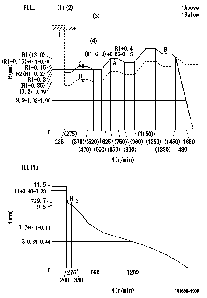
N:Pump speed
R:Rack position (mm)
(1)Torque cam stamping: T1
(2)Tolerance for racks not indicated: +-0.05mm.
(3)RACK LIMIT
(4)Boost compensator stroke: BCL
----------
T1=M68 BCL=1.15+-0.1mm
----------
----------
T1=M68 BCL=1.15+-0.1mm
----------
Speed control lever angle

F:Full speed
I:Idle
(1)Use the hole at R = aa
(2)Stopper bolt set position 'H'
----------
aa=36mm
----------
a=26deg+-5deg b=39deg+-3deg
----------
aa=36mm
----------
a=26deg+-5deg b=39deg+-3deg
Stop lever angle
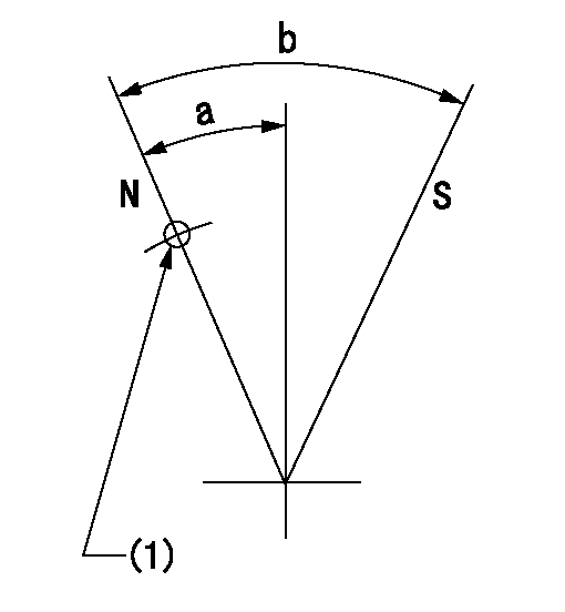
N:Pump normal
S:Stop the pump.
(1)Use the pin at R = aa
----------
aa=42mm
----------
a=27deg+-5deg b=40deg+-5deg
----------
aa=42mm
----------
a=27deg+-5deg b=40deg+-5deg
Timing setting

(1)Pump vertical direction
(2)Position of timer's threaded hole at No 1 cylinder's beginning of injection
(3)-
(4)-
----------
----------
a=(60deg)
----------
----------
a=(60deg)
Information:
Test Procedure
System Operation
The SLC 5/04 diagnostic indicators are located on the front of the following components: Power Supply, CPU and I/O Modules.The diagnostic indicators help trace the source of the fault. Faults can be found in the following components: Input devices, Output devices, Wiring and The controller.The "FLT" LED is illuminated and the outputs of the controller are de-energized. The power to a chassis is lost.The red "FLT" LED is illuminated. There is a fatal error. A fatal error indicates that the processor is not communicating.The red "FLT" LED is flashing during operation. The processor detects a major fault. The fault is in the processor expansion chassis or the fault is in the memory.The green "RS232" LED is illuminated in the DH+ mode. The communications active bit (S:17) is set in the "System Status" file. The processor is communicating on the network.The green "RS232" LED is flashing in the DH+ mode. The processor cannot establish communication because there are no active nodes on the network.The "RS232" LED is extinguished in the DH+ mode. A fatal error is present.
Illustration 1 g00563574
Diagram of the LED indicators
Illustration 2 g00563507
Functional Test
Check the electrical connectors and check the wiring.
Bodily contact with electrical potential can cause bodily injury or death.To avoid the possibility of injury or death, ensure that the main power supply has been disconnected before performing any maintenance or removing any modules.
Disconnect the power supply.
Check the electrical connectors and check the wiring for damage or bad connections.
Verify that all modules are properly seated.
Verify the status of the LED on the SLC 5/04.The results of the preceding procedure are in the following list:
All of the components are fully installed. All of the components are free of corrosion. All of the components are free of damage. All of the modules are properly seated. Proceed to 2.
The components are not fully installed. The components are not free of corrosion. The components are damaged. All of the modules are not properly seated. Repair the component. Verify that the repair resolves the problem. STOP.
Check the line voltage.
Reconnect the power supply.
Measure the line voltage at the terminals.
Verify the voltage of the power supply. The power supply voltage should be measured between 21.0 VDC and 28.0 VDC.The results of the preceding procedure are in the following list:
The line voltage is in the range. Proceed to 3.
The line voltage is out of the range. Refer to Troubleshooting, "System Power". Stop.
Cycle the power.
Secure power to the PLC.
Energize the PLC.The results of the preceding procedure are in the following list:
No errors are displayed on the LED indicators. Stop.
Errors are displayed on the LED indicators. Refer to Maintenance Procedure, "Processor - Replace". Stop.
Have questions with 101696-9990?
Group cross 101696-9990 ZEXEL
Nissan-Diesel
Nissan-Diesel
Nissan-Diesel
101696-9990
9 400 616 166
16713Z6871
INJECTION-PUMP ASSEMBLY
FE6T
FE6T