Information injection-pump assembly
BOSCH
9 400 611 449
9400611449
ZEXEL
101696-9940
1016969940
Rating:
Service parts 101696-9940 INJECTION-PUMP ASSEMBLY:
1.
_

7.
COUPLING PLATE
8.
_
9.
_
11.
Nozzle and Holder
16600-95015
12.
Open Pre:MPa(Kqf/cm2)
19.6{200}
15.
NOZZLE SET
Cross reference number
BOSCH
9 400 611 449
9400611449
ZEXEL
101696-9940
1016969940
Zexel num
Bosch num
Firm num
Name
Calibration Data:
Adjustment conditions
Test oil
1404 Test oil ISO4113 or {SAEJ967d}
1404 Test oil ISO4113 or {SAEJ967d}
Test oil temperature
degC
40
40
45
Nozzle and nozzle holder
105780-8140
Bosch type code
EF8511/9A
Nozzle
105780-0000
Bosch type code
DN12SD12T
Nozzle holder
105780-2080
Bosch type code
EF8511/9
Opening pressure
MPa
17.2
Opening pressure
kgf/cm2
175
Injection pipe
Outer diameter - inner diameter - length (mm) mm 6-2-600
Outer diameter - inner diameter - length (mm) mm 6-2-600
Overflow valve
131424-1520
Overflow valve opening pressure
kPa
157
123
191
Overflow valve opening pressure
kgf/cm2
1.6
1.25
1.95
Tester oil delivery pressure
kPa
157
157
157
Tester oil delivery pressure
kgf/cm2
1.6
1.6
1.6
Direction of rotation (viewed from drive side)
Right R
Right R
Injection timing adjustment
Direction of rotation (viewed from drive side)
Right R
Right R
Injection order
1-4-2-6-
3-5
Pre-stroke
mm
3.7
3.65
3.75
Beginning of injection position
Drive side NO.1
Drive side NO.1
Difference between angles 1
Cal 1-4 deg. 60 59.5 60.5
Cal 1-4 deg. 60 59.5 60.5
Difference between angles 2
Cyl.1-2 deg. 120 119.5 120.5
Cyl.1-2 deg. 120 119.5 120.5
Difference between angles 3
Cal 1-6 deg. 180 179.5 180.5
Cal 1-6 deg. 180 179.5 180.5
Difference between angles 4
Cal 1-3 deg. 240 239.5 240.5
Cal 1-3 deg. 240 239.5 240.5
Difference between angles 5
Cal 1-5 deg. 300 299.5 300.5
Cal 1-5 deg. 300 299.5 300.5
Injection quantity adjustment
Adjusting point
-
Rack position
13.5
Pump speed
r/min
1400
1400
1400
Average injection quantity
mm3/st.
108.5
106.9
110.1
Max. variation between cylinders
%
0
-3.5
3.5
Basic
*
Fixing the rack
*
Standard for adjustment of the maximum variation between cylinders
*
Injection quantity adjustment_02
Adjusting point
H
Rack position
9.5+-0.5
Pump speed
r/min
275
275
275
Average injection quantity
mm3/st.
8
6.2
9.8
Max. variation between cylinders
%
0
-10
10
Fixing the rack
*
Standard for adjustment of the maximum variation between cylinders
*
Injection quantity adjustment_03
Adjusting point
A
Rack position
R1(13.5)
Pump speed
r/min
1400
1400
1400
Average injection quantity
mm3/st.
108.5
107.5
109.5
Basic
*
Fixing the lever
*
Boost pressure
kPa
32
32
Boost pressure
mmHg
240
240
Injection quantity adjustment_04
Adjusting point
B
Rack position
R1-0.05
Pump speed
r/min
800
800
800
Average injection quantity
mm3/st.
101
97.8
104.2
Fixing the lever
*
Boost pressure
kPa
32
32
Boost pressure
mmHg
240
240
Injection quantity adjustment_05
Adjusting point
C
Rack position
12.2+-0.
5
Pump speed
r/min
400
400
400
Average injection quantity
mm3/st.
57.5
55.5
59.5
Fixing the lever
*
Boost pressure
kPa
0
0
0
Boost pressure
mmHg
0
0
0
Injection quantity adjustment_06
Adjusting point
I
Rack position
-
Pump speed
r/min
150
150
150
Average injection quantity
mm3/st.
85
85
105
Fixing the lever
*
Boost pressure
kPa
0
0
0
Boost pressure
mmHg
0
0
0
Rack limit
*
Boost compensator adjustment
Pump speed
r/min
550
550
550
Rack position
R2-1.45
Boost pressure
kPa
3.3
2
4.6
Boost pressure
mmHg
25
15
35
Boost compensator adjustment_02
Pump speed
r/min
550
550
550
Rack position
R2-1.15
Boost pressure
kPa
6.7
5.4
8
Boost pressure
mmHg
50
40
60
Boost compensator adjustment_03
Pump speed
r/min
550
550
550
Rack position
R2[R1-0.
6]
Boost pressure
kPa
18.7
18.7
18.7
Boost pressure
mmHg
140
140
140
Timer adjustment
Pump speed
r/min
920--
Advance angle
deg.
0
0
0
Remarks
Start
Start
Timer adjustment_02
Pump speed
r/min
870
Advance angle
deg.
0.5
Timer adjustment_03
Pump speed
r/min
1400
Advance angle
deg.
2
1.5
2.5
Remarks
Finish
Finish
Test data Ex:
Governor adjustment
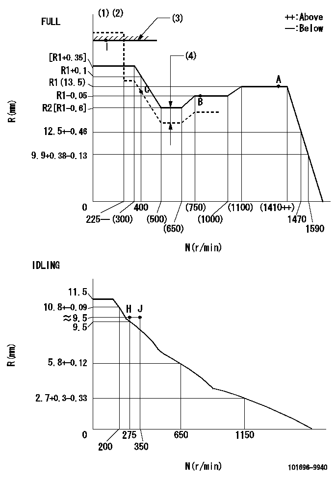
N:Pump speed
R:Rack position (mm)
(1)Torque cam stamping: T1
(2)Tolerance for racks not indicated: +-0.05mm.
(3)RACK LIMIT
(4)Boost compensator stroke: BCL
----------
T1=N07 BCL=1.45+-0.1mm
----------
----------
T1=N07 BCL=1.45+-0.1mm
----------
Speed control lever angle

F:Full speed
I:Idle
(1)Use the hole at R = aa
(2)Stopper bolt setting
----------
aa=100mm
----------
a=26.5deg+-5deg b=43deg+-3deg
----------
aa=100mm
----------
a=26.5deg+-5deg b=43deg+-3deg
Stop lever angle
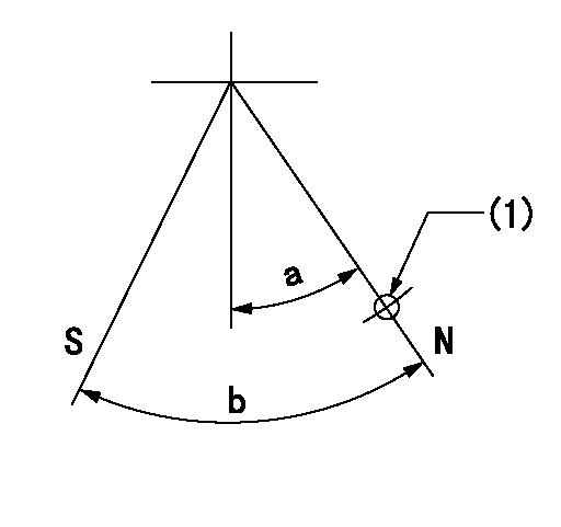
N:Pump normal
S:Stop the pump.
(1)Use the hole at R = aa
----------
aa=36mm
----------
a=20deg+-5deg b=40deg+-5deg
----------
aa=36mm
----------
a=20deg+-5deg b=40deg+-5deg
Timing setting

(1)Pump vertical direction
(2)Coupling's key groove position at No 1 cylinder's beginning of injection
(3)-
(4)-
----------
----------
a=(40deg)
----------
----------
a=(40deg)
Information:
Accidental engine starting can cause injury or death to personnel working on the equipment.To avoid accidental engine starting, disconnect the battery cable from the negative (−) battery terminal. Completely tape all metal surfaces of the disconnected battery cable end in order to prevent contact with other metal surfaces which could activate the engine electrical system.Place a Do Not Operate tag at the Start/Stop switch location to inform personnel that the equipment is being worked on.
2301A Electric Governor Control
The 2301A Electric Governor Control activates all of the components that are in the electric protection system. The components are activated in the same manner when the nonelectric governor is used. One difference exists in the main circuit. The fuel shutoff solenoid (FSOS) (line 43) is not used.When the electric governor control is used, the engine must run in a normal condition in order for the electric circuit to operate in the manner that is described below.
Current flows from the terminals (TS-28) (line 43) and (TS-31) (line 44), which are located on the terminal strip in the junction box.
Current from terminals (TS-28) (line 43) and (TS-31) (line 44) flows through the preregulator (PR) (line 48) or the fuse (F4) to the electric governor control.
When the engine flywheel is rotating, the current also flows through the electric governor actuator (EGA) (line 52). When a fault in the system causes the current to energize the slave relay (SR1), the following events occur in the electric circuit in order to stop the engine.
The slave relay (SR1) opens across the contacts (SR1-30) and (SR1-87a) (line 45). The relay closes across the contacts (SR1-30) and (SR1-87) (line 43).
When the circuit opens across contacts (SR1-30) and (SR1-87a), the current is stopped to the electric governor control.
Current to the electric governor actuator (EGA) is also stopped.
The mechanical spring load in the electric governor actuator (EGA) will now move the fuel control rod in order to stop fuel flow to the engine. Note: With the exception of the differences that are described in this section of the manual, all of the fault circuits in the electric protection system are identical for the 2301A Electric Governor Control and for the nonelectric governor control.
Illustration 5 g00292615
Junction Box Wiring for ETR protection system with OP, WT, and OS that does not require