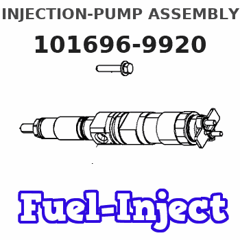
Information injection-pump assembly
BOSCH
9 400 616 162
9400616162
ZEXEL
101696-9920
1016969920
NISSAN-DIESEL
16713Z6807
16713z6807
Rating:
Include in #1:
106871-2890
as _
Cross reference number
BOSCH
9 400 616 162
9400616162
ZEXEL
101696-9920
1016969920
NISSAN-DIESEL
16713Z6807
16713z6807
Zexel num
Bosch num
Firm num
Name
101696-9920
9 400 616 162
16713Z6807 NISSAN-DIESEL
INJECTION-PUMP ASSEMBLY
FE6T K
FE6T K
Calibration Data:
Adjustment conditions
Test oil
1404 Test oil ISO4113 or {SAEJ967d}
1404 Test oil ISO4113 or {SAEJ967d}
Test oil temperature
degC
40
40
45
Nozzle and nozzle holder
105780-8140
Bosch type code
EF8511/9A
Nozzle
105780-0000
Bosch type code
DN12SD12T
Nozzle holder
105780-2080
Bosch type code
EF8511/9
Opening pressure
MPa
17.2
Opening pressure
kgf/cm2
175
Injection pipe
Outer diameter - inner diameter - length (mm) mm 6-2-600
Outer diameter - inner diameter - length (mm) mm 6-2-600
Overflow valve
134424-1520
Overflow valve opening pressure
kPa
162
147
177
Overflow valve opening pressure
kgf/cm2
1.65
1.5
1.8
Tester oil delivery pressure
kPa
157
157
157
Tester oil delivery pressure
kgf/cm2
1.6
1.6
1.6
Direction of rotation (viewed from drive side)
Right R
Right R
Injection timing adjustment
Direction of rotation (viewed from drive side)
Right R
Right R
Injection order
1-4-2-6-
3-5
Pre-stroke
mm
3.9
3.85
3.95
Beginning of injection position
Drive side NO.1
Drive side NO.1
Difference between angles 1
Cal 1-4 deg. 60 59.5 60.5
Cal 1-4 deg. 60 59.5 60.5
Difference between angles 2
Cyl.1-2 deg. 120 119.5 120.5
Cyl.1-2 deg. 120 119.5 120.5
Difference between angles 3
Cal 1-6 deg. 180 179.5 180.5
Cal 1-6 deg. 180 179.5 180.5
Difference between angles 4
Cal 1-3 deg. 240 239.5 240.5
Cal 1-3 deg. 240 239.5 240.5
Difference between angles 5
Cal 1-5 deg. 300 299.5 300.5
Cal 1-5 deg. 300 299.5 300.5
Injection quantity adjustment
Adjusting point
-
Rack position
13.6
Pump speed
r/min
700
700
700
Average injection quantity
mm3/st.
92.5
90.5
94.5
Max. variation between cylinders
%
0
-3.5
3.5
Basic
*
Fixing the rack
*
Standard for adjustment of the maximum variation between cylinders
*
Injection quantity adjustment_02
Adjusting point
H
Rack position
9.7+-0.5
Pump speed
r/min
275
275
275
Average injection quantity
mm3/st.
17
15.2
18.8
Max. variation between cylinders
%
0
-10
10
Fixing the rack
*
Standard for adjustment of the maximum variation between cylinders
*
Injection quantity adjustment_03
Adjusting point
A
Rack position
R1(13.6)
Pump speed
r/min
700
700
700
Average injection quantity
mm3/st.
92.5
91.5
93.5
Basic
*
Fixing the lever
*
Boost pressure
kPa
40
40
Boost pressure
mmHg
300
300
Injection quantity adjustment_04
Adjusting point
B
Rack position
(R1+0.3)
+0.05-0.
15
Pump speed
r/min
1400
1400
1400
Average injection quantity
mm3/st.
99.5
96.3
102.7
Fixing the lever
*
Boost pressure
kPa
40
40
Boost pressure
mmHg
300
300
Injection quantity adjustment_05
Adjusting point
C
Rack position
R2(R1-0.
2)
Pump speed
r/min
420
420
420
Average injection quantity
mm3/st.
80
76.8
83.2
Fixing the lever
*
Boost pressure
kPa
40
40
Boost pressure
mmHg
300
300
Injection quantity adjustment_06
Adjusting point
D
Rack position
R2-1.8
Pump speed
r/min
420
420
420
Average injection quantity
mm3/st.
46
44
48
Fixing the lever
*
Boost pressure
kPa
0
0
0
Boost pressure
mmHg
0
0
0
Injection quantity adjustment_07
Adjusting point
I
Rack position
-
Pump speed
r/min
150
150
150
Average injection quantity
mm3/st.
105
105
125
Fixing the lever
*
Boost pressure
kPa
0
0
0
Boost pressure
mmHg
0
0
0
Rack limit
*
Boost compensator adjustment
Pump speed
r/min
420
420
420
Rack position
R2-1.8
Boost pressure
kPa
12
10.7
13.3
Boost pressure
mmHg
90
80
100
Boost compensator adjustment_02
Pump speed
r/min
420
420
420
Rack position
R2(R1-0.
2)
Boost pressure
kPa
26.7
26.7
26.7
Boost pressure
mmHg
200
200
200
Timer adjustment
Pump speed
r/min
1170--
Advance angle
deg.
0
0
0
Remarks
Start
Start
Timer adjustment_02
Pump speed
r/min
1120
Advance angle
deg.
0.5
Timer adjustment_03
Pump speed
r/min
1400
Advance angle
deg.
3
2.5
3.5
Remarks
Finish
Finish
Test data Ex:
Governor adjustment
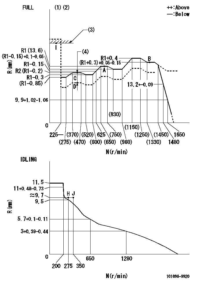
N:Pump speed
R:Rack position (mm)
(1)Torque cam stamping: T1
(2)Tolerance for racks not indicated: +-0.05mm.
(3)RACK LIMIT
(4)Boost compensator stroke: BCL
----------
T1=M68 BCL=1.8+-0.1mm
----------
----------
T1=M68 BCL=1.8+-0.1mm
----------
Speed control lever angle

F:Full speed
I:Idle
(1)Use the hole at R = aa
(2)Stopper bolt set position 'H'
----------
aa=41.5mm
----------
a=26deg+-5deg b=39deg+-3deg
----------
aa=41.5mm
----------
a=26deg+-5deg b=39deg+-3deg
Stop lever angle
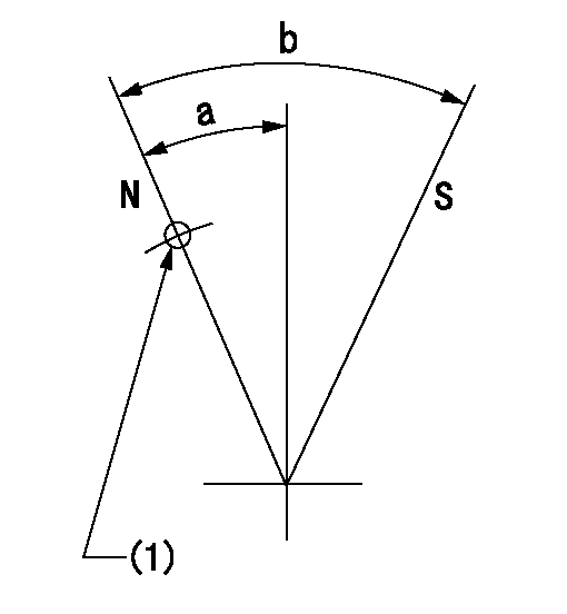
N:Pump normal
S:Stop the pump.
(1)Use the pin at R = aa
----------
aa=42mm
----------
a=27deg+-5deg b=40deg+-5deg
----------
aa=42mm
----------
a=27deg+-5deg b=40deg+-5deg
Timing setting

(1)Pump vertical direction
(2)Position of timer's threaded hole at No 1 cylinder's beginning of injection
(3)-
(4)-
----------
----------
a=(60deg)
----------
----------
a=(60deg)
Information:
Introduction
The problem that is identified below does not have a permanent solution. Until a permanent solution is known, use the solution that is listed below.Problem
A significant amount of HEUI pumps and injectors have been returned, but no cause of failure can be determined.Solution
Diagnostic procedures have been updated and have been incorporated into the following publications:
Special Instruction, REHS3819, "Procedure for Troubleshooting and Cleaning the Oil Rail System for the Hydraulic Electronic Unit Injector (HEUI)"
Troubleshooting, "Injection Actuation Pressure - Test"Note: These publications have been translated into Mandarin and Spanish.In addition, a new troubleshooting checklist is included with all service repair for HUEI pumps and HEUI injectors. The checklist is a summary of the diagnostic procedure steps to be confirmed before a suspect component is replaced. The checklist must be completed and returned with the suspect components in order to aid engineering to determine the cause of failure.Following the instructions step-by-step is critical in order to diagnose the failed component correctly. Do not skip steps in the procedures. Skipping steps in the procedure will lead to incorrect diagnosis of the problem.
Have questions with 101696-9920?
Group cross 101696-9920 ZEXEL
Nissan-Diesel
Nissan-Diesel
101696-9920
9 400 616 162
16713Z6807
INJECTION-PUMP ASSEMBLY
FE6T
FE6T