Information injection-pump assembly
ZEXEL
101696-9910
1016969910
NISSAN-DIESEL
16713Z6803
16713z6803

Rating:
Service parts 101696-9910 INJECTION-PUMP ASSEMBLY:
1.
_

7.
COUPLING PLATE
8.
_
9.
_
11.
Nozzle and Holder
16600-Z5672
12.
Open Pre:MPa(Kqf/cm2)
16.7{170}/19.6{200}
14.
NOZZLE
Cross reference number
ZEXEL
101696-9910
1016969910
NISSAN-DIESEL
16713Z6803
16713z6803
Zexel num
Bosch num
Firm num
Name
Calibration Data:
Adjustment conditions
Test oil
1404 Test oil ISO4113 or {SAEJ967d}
1404 Test oil ISO4113 or {SAEJ967d}
Test oil temperature
degC
40
40
45
Nozzle and nozzle holder
105780-8260
Bosch type code
9 430 610 133
Nozzle
105780-0120
Bosch type code
1 688 901 990
Nozzle holder
105780-2190
Opening pressure
MPa
18
Opening pressure
kgf/cm2
184
Injection pipe
Outer diameter - inner diameter - length (mm) mm 6-2-600
Outer diameter - inner diameter - length (mm) mm 6-2-600
Overflow valve
131425-0420
Overflow valve opening pressure
kPa
157
123
191
Overflow valve opening pressure
kgf/cm2
1.6
1.25
1.95
Tester oil delivery pressure
kPa
255
255
255
Tester oil delivery pressure
kgf/cm2
2.6
2.6
2.6
Direction of rotation (viewed from drive side)
Right R
Right R
Injection timing adjustment
Direction of rotation (viewed from drive side)
Right R
Right R
Injection order
1-4-2-6-
3-5
Pre-stroke
mm
3.1
3.05
3.15
Beginning of injection position
Drive side NO.1
Drive side NO.1
Difference between angles 1
Cal 1-4 deg. 60 59.5 60.5
Cal 1-4 deg. 60 59.5 60.5
Difference between angles 2
Cyl.1-2 deg. 120 119.5 120.5
Cyl.1-2 deg. 120 119.5 120.5
Difference between angles 3
Cal 1-6 deg. 180 179.5 180.5
Cal 1-6 deg. 180 179.5 180.5
Difference between angles 4
Cal 1-3 deg. 240 239.5 240.5
Cal 1-3 deg. 240 239.5 240.5
Difference between angles 5
Cal 1-5 deg. 300 299.5 300.5
Cal 1-5 deg. 300 299.5 300.5
Injection quantity adjustment
Adjusting point
-
Rack position
13.1
Pump speed
r/min
700
700
700
Average injection quantity
mm3/st.
105
103.4
106.6
Max. variation between cylinders
%
0
-3.5
3.5
Basic
*
Fixing the rack
*
Standard for adjustment of the maximum variation between cylinders
*
Injection quantity adjustment_02
Adjusting point
Z
Rack position
9.2+-0.5
Pump speed
r/min
400
400
400
Average injection quantity
mm3/st.
20
18.2
21.8
Max. variation between cylinders
%
0
-10
10
Fixing the rack
*
Standard for adjustment of the maximum variation between cylinders
*
Injection quantity adjustment_03
Adjusting point
A
Rack position
R1(13.1)
Pump speed
r/min
700
700
700
Average injection quantity
mm3/st.
105
104
106
Basic
*
Fixing the lever
*
Boost pressure
kPa
32.7
32.7
Boost pressure
mmHg
245
245
Injection quantity adjustment_04
Adjusting point
B
Rack position
R1+1.35
Pump speed
r/min
1400
1400
1400
Average injection quantity
mm3/st.
106
102
110
Fixing the lever
*
Boost pressure
kPa
32.7
32.7
Boost pressure
mmHg
245
245
Injection quantity adjustment_05
Adjusting point
D
Rack position
(R2-1.5)
Pump speed
r/min
400
400
400
Average injection quantity
mm3/st.
76.5
74.5
78.5
Fixing the lever
*
Boost pressure
kPa
0
0
0
Boost pressure
mmHg
0
0
0
Injection quantity adjustment_06
Adjusting point
I
Rack position
-
Pump speed
r/min
150
150
150
Average injection quantity
mm3/st.
140
140
150
Fixing the lever
*
Boost pressure
kPa
0
0
0
Boost pressure
mmHg
0
0
0
Rack limit
*
Boost compensator adjustment
Pump speed
r/min
400
400
400
Rack position
(R2-1.5)
Boost pressure
kPa
6.7
5.4
8
Boost pressure
mmHg
50
40
60
Boost compensator adjustment_02
Pump speed
r/min
400
400
400
Rack position
R2(R1+0.
05)
Boost pressure
kPa
19.3
19.3
19.3
Boost pressure
mmHg
145
145
145
Timer adjustment
Pump speed
r/min
-
Advance angle
deg.
1
0.5
1.5
Remarks
Measure speed (beginning of operation).
Measure speed (beginning of operation).
Timer adjustment_02
Pump speed
r/min
-
Advance angle
deg.
0
0
0
Remarks
Measure the actual speed.
Measure the actual speed.
Timer adjustment_03
Pump speed
r/min
-
Advance angle
deg.
0
0
0
Remarks
Measure the actual speed.
Measure the actual speed.
Timer adjustment_04
Pump speed
r/min
-
Advance angle
deg.
4.5
4
5
Remarks
Measure the actual speed, stop
Measure the actual speed, stop
Test data Ex:
Governor adjustment
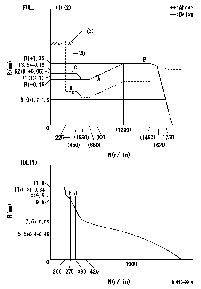
N:Pump speed
R:Rack position (mm)
(1)Torque cam stamping: T1
(2)Tolerance for racks not indicated: +-0.05mm.
(3)RACK LIMIT
(4)Boost compensator stroke: BCL
----------
T1=M83 BCL=(1.5)mm
----------
----------
T1=M83 BCL=(1.5)mm
----------
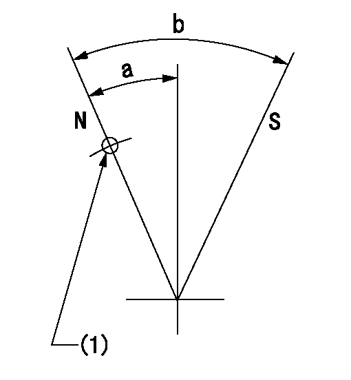
Speed control lever angle

F:Full speed
I:Idle
(1)Use the hole at R = aa
(2)Stopper bolt set position 'H'
----------
aa=39mm
----------
a=20deg+-5deg b=41deg+-3deg
----------
aa=39mm
----------
a=20deg+-5deg b=41deg+-3deg
Stop lever angle
N:Pump normal
S:Stop the pump.
(1)Use the pin at R = aa
----------
aa=42mm
----------
a=25deg+-5deg b=40deg+-5deg
----------
aa=42mm
----------
a=25deg+-5deg b=40deg+-5deg
0000001501 RACK SENSOR
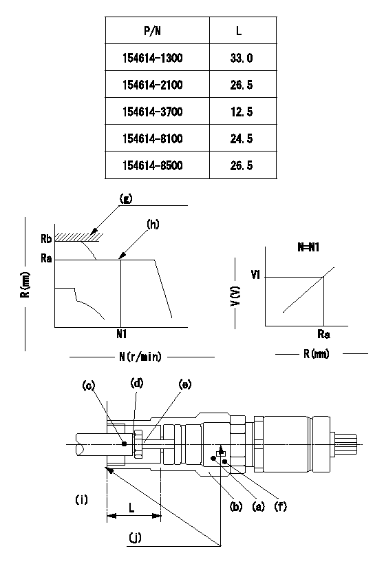
(g) rack limit
(h) rack sensor performance confirmation position
(i) pump end face
(j) Apply red paint.
Rack sensor adjustment (-5*20, threaded type, with A type rack limiter)
1. Rack limit adjustment
(1)When installing joint (b), select a shim (d) so that the rack limit rack position is Rb and the injection quantity is Qa.
(2)Install rod (E) to the rack (c).
(3)Select a joint (b) from the table above so that the distance from the pump end face to the rod (e) is L - 0.2 mm at rack position Rb.
2. Rack sensor adjustment
(1)Screw in the bobbin (A) until it contacts the joint (B).
(2)Fix the lever and set the pump speed at N1 and the rack position at Ra.
(3)Adjust the amount that the bobbin (a) is screwed in so that the amp's output voltage is V1. Then, fix using nut (f).
(4)Set the lever at the full speed side and confirm that the amp's output voltage is V1.
(5)Stick the caution plate on the top of the joint and apply red paint to the joint (b) and nut (f) join, and to the pump end face and joint (b) join.
Speed N1, Rack position = Ra, output voltage V1+-0.01 (V), rack sensor supply voltage 5+-0.01 (V)
----------
Qa=140+10mm3/st Ra=R1(13.1)mm N1=700r/min V1=3+-0.01V
----------
----------
Qa=140+10mm3/st Ra=R1(13.1)mm N1=700r/min V1=3+-0.01V
----------
0000001601 LEVER
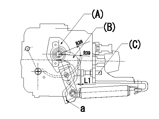
(a) Speed lever
(B) Accelerator lever
(C) Accelerator lever stopper bolt
1. Accelerator lever setting method
With the speed lever in the idling position, back off the accelerator lever stopper bolt L1 from where it contacts point a. (Back off 1+0.5 turns and set.)
----------
L1=1+0.5mm
----------
----------
L1=1+0.5mm
----------
Timing setting

(1)Pump vertical direction
(2)Position of timer's threaded hole at No 1 cylinder's beginning of injection
(3)-
(4)-
----------
----------
a=(60deg)
----------
----------
a=(60deg)
Information:
Self-Diagnostics
The electronic system has self-diagnostic capabilities. When a problem is detected, a fault indicator is illuminated on the front of the module. A panel of indicators is also located on the MECP.Module Fault Indicators
A fault should be immediately serviced. A fault indicator is illuminated when a problem exists. When the PLC has an active fault, find the appropriate procedure in the troubleshooting section.Operating Information that is Stored in the Programmable Logic Controller
The SLC 5/04 uses a battery in order to provide backup power to the C-MOS RAM.Programmable Logic Controller Chassis or Rack
The PLC chassis contains the following components:
Power Supply
CPU Module
Input Modules
Output Modules
User Defined ModulesThe system uses the Allen-Bradley SLC 500 series of PLC.Central Processing Unit
Illustration 1 g00562937
The SLC 5/04 processor includes a three-position keyswitch on the front panel. The key switches the system from the following three modes of operation: RUN, PROGRAM and REMOTEThe key can be removed in each of the three positions. The mode changes when the position of the key is switched from the RUN position. Do not substitute the keyswitch for a master control relay. Do not substitute the keyswitch for an emergency stop switch.RUN Position
The RUN position places the processor in the run mode. The processor conducts the following functions:
The processor scans the ladder program.
The processor executes the ladder program.
The processor monitors input devices.
The processor energizes the output devices.
The processor acts on the enabled I/O forces.You can only change the processor's mode with the keyswitch. Revising of the program cannot be performed when you are on-line."PROG" Position
The Program position places the processor in the program mode. The processor does not scan the program and the processor does not execute the program. The controller's outputs are de-energized.You can only change the processor's mode with the keyswitch. Revising of the program can be performed when you are on-line.When the keyswitch is in the program position, a qualified technician can use the programmer interface device in order to change the processor's mode.Remote Position
The remote position places the processor in the remote mode. You can only change the processor's mode with the keyswitch. Revising of the program can be performed when you are on-line.When the keyswitch is in the remote position, a qualified technician can use the programmer interface device in order to change the processor's mode.Processor's Fault Indicators
A fault should be immediately serviced. A fault indicator is illuminated when a problem exists. When the PLC has an active fault, find the appropriate procedure in the troubleshooting section.The Processor's Indicators
Six LED indicators are on the front of the CPU module. The indicators show the operating status of your processor. The indicators have the labels that are in the following list:"RUN", "FLT", "BATT", "FORCE", "DH+" and "RS232"Thermocouple Module
The thermocouple module contains diagnostic features that can identify sources of problems. The problems may occur during power up. The problems may occur during normal operation. Each channel can receive a signal from the sensors or from the analog input devices.
Illustration 2 g00562940
LED indicatorsResistance Temperature Detector Module
The RTD module contains diagnostic features that