Information injection-pump assembly
BOSCH
9 400 616 159
9400616159
ZEXEL
101696-9893
1016969893
NISSAN-DIESEL
16713Z6963
16713z6963
Rating:
Include in #1:
106691-2011
as _
Cross reference number
BOSCH
9 400 616 159
9400616159
ZEXEL
101696-9893
1016969893
NISSAN-DIESEL
16713Z6963
16713z6963
Zexel num
Bosch num
Firm num
Name
101696-9893
9 400 616 159
16713Z6963 NISSAN-DIESEL
INJECTION-PUMP ASSEMBLY
FE6TA K
FE6TA K
Calibration Data:
Adjustment conditions
Test oil
1404 Test oil ISO4113 or {SAEJ967d}
1404 Test oil ISO4113 or {SAEJ967d}
Test oil temperature
degC
40
40
45
Nozzle and nozzle holder
105780-8260
Bosch type code
9 430 610 133
Nozzle
105780-0120
Bosch type code
1 688 901 990
Nozzle holder
105780-2190
Opening pressure
MPa
18
Opening pressure
kgf/cm2
184
Injection pipe
Outer diameter - inner diameter - length (mm) mm 6-2-600
Outer diameter - inner diameter - length (mm) mm 6-2-600
Overflow valve
131425-0420
Overflow valve opening pressure
kPa
157
123
191
Overflow valve opening pressure
kgf/cm2
1.6
1.25
1.95
Tester oil delivery pressure
kPa
255
255
255
Tester oil delivery pressure
kgf/cm2
2.6
2.6
2.6
Direction of rotation (viewed from drive side)
Right R
Right R
Injection timing adjustment
Direction of rotation (viewed from drive side)
Right R
Right R
Injection order
1-4-2-6-
3-5
Pre-stroke
mm
3.1
3.05
3.15
Beginning of injection position
Drive side NO.1
Drive side NO.1
Difference between angles 1
Cal 1-4 deg. 60 59.5 60.5
Cal 1-4 deg. 60 59.5 60.5
Difference between angles 2
Cyl.1-2 deg. 120 119.5 120.5
Cyl.1-2 deg. 120 119.5 120.5
Difference between angles 3
Cal 1-6 deg. 180 179.5 180.5
Cal 1-6 deg. 180 179.5 180.5
Difference between angles 4
Cal 1-3 deg. 240 239.5 240.5
Cal 1-3 deg. 240 239.5 240.5
Difference between angles 5
Cal 1-5 deg. 300 299.5 300.5
Cal 1-5 deg. 300 299.5 300.5
Injection quantity adjustment
Adjusting point
-
Rack position
12.9
Pump speed
r/min
700
700
700
Average injection quantity
mm3/st.
102
100.4
103.6
Max. variation between cylinders
%
0
-3.5
3.5
Basic
*
Fixing the rack
*
Standard for adjustment of the maximum variation between cylinders
*
Injection quantity adjustment_02
Adjusting point
Z
Rack position
9.2+-0.5
Pump speed
r/min
400
400
400
Average injection quantity
mm3/st.
20
18.2
21.8
Max. variation between cylinders
%
0
-10
10
Fixing the rack
*
Standard for adjustment of the maximum variation between cylinders
*
Injection quantity adjustment_03
Adjusting point
A
Rack position
R1(12.9)
Pump speed
r/min
700
700
700
Average injection quantity
mm3/st.
102
101
103
Basic
*
Fixing the lever
*
Boost pressure
kPa
33.3
33.3
Boost pressure
mmHg
250
250
Injection quantity adjustment_04
Adjusting point
B
Rack position
R1+1.15
Pump speed
r/min
1400
1400
1400
Average injection quantity
mm3/st.
100
96
104
Fixing the lever
*
Boost pressure
kPa
33.3
33.3
Boost pressure
mmHg
250
250
Injection quantity adjustment_05
Adjusting point
C
Rack position
R2(R1+0.
15)
Pump speed
r/min
400
400
400
Average injection quantity
mm3/st.
114.5
110.5
118.5
Fixing the lever
*
Boost pressure
kPa
33.3
33.3
Boost pressure
mmHg
250
250
Injection quantity adjustment_06
Adjusting point
D
Rack position
(R2-1.4)
Pump speed
r/min
400
400
400
Average injection quantity
mm3/st.
73.5
71.5
75.5
Fixing the lever
*
Boost pressure
kPa
0
0
0
Boost pressure
mmHg
0
0
0
Injection quantity adjustment_07
Adjusting point
I
Rack position
-
Pump speed
r/min
150
150
150
Average injection quantity
mm3/st.
120
120
130
Fixing the lever
*
Boost pressure
kPa
0
0
0
Boost pressure
mmHg
0
0
0
Rack limit
*
Boost compensator adjustment
Pump speed
r/min
400
400
400
Rack position
(R2-1.4)
Boost pressure
kPa
6.7
5.4
8
Boost pressure
mmHg
50
40
60
Boost compensator adjustment_02
Pump speed
r/min
400
400
400
Rack position
R2(R1+0.
15)
Boost pressure
kPa
20
20
20
Boost pressure
mmHg
150
150
150
Timer adjustment
Pump speed
r/min
-
Advance angle
deg.
1
0.5
1.5
Remarks
Measure speed (beginning of operation).
Measure speed (beginning of operation).
Timer adjustment_02
Pump speed
r/min
-
Advance angle
deg.
0
0
0
Remarks
Measure the actual speed.
Measure the actual speed.
Timer adjustment_03
Pump speed
r/min
-
Advance angle
deg.
0
0
0
Remarks
Measure the actual speed.
Measure the actual speed.
Timer adjustment_04
Pump speed
r/min
-
Advance angle
deg.
4.5
4
5
Remarks
Measure the actual speed, stop
Measure the actual speed, stop
Test data Ex:
Governor adjustment
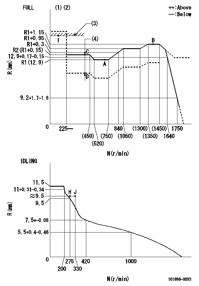
N:Pump speed
R:Rack position (mm)
(1)Torque cam stamping: T1
(2)Tolerance for racks not indicated: +-0.05mm.
(3)RACK LIMIT
(4)Boost compensator stroke: BCL
----------
T1=M71 BCL=(1.4)mm
----------
----------
T1=M71 BCL=(1.4)mm
----------
Speed control lever angle

F:Full speed
I:Idle
(1)Use the hole at R = aa
(2)Stopper bolt set position 'H'
----------
aa=39mm
----------
a=20deg+-5deg b=40.5deg+-3deg
----------
aa=39mm
----------
a=20deg+-5deg b=40.5deg+-3deg
Stop lever angle
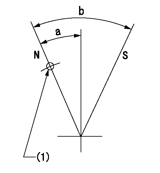
N:Pump normal
S:Stop the pump.
(1)Use the pin at R = aa
----------
aa=42mm
----------
a=25deg+-5deg b=40deg+-5deg
----------
aa=42mm
----------
a=25deg+-5deg b=40deg+-5deg
0000001501 RACK SENSOR
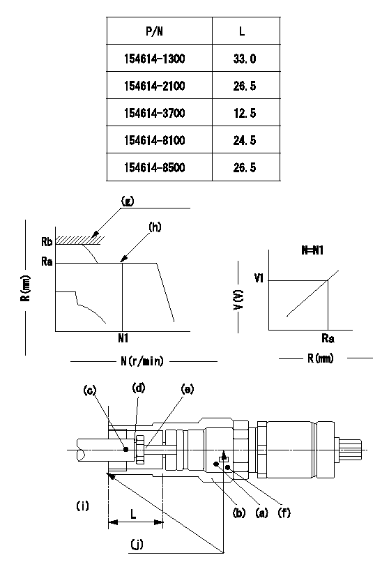
(g) rack limit
(h) rack sensor performance confirmation position
(i) pump end face
(j) Apply red paint.
Rack sensor adjustment (-5*20, threaded type, with A type rack limiter)
1. Rack limit adjustment
(1)When installing joint (b), select a shim (d) so that the rack limit rack position is Rb and the injection quantity is Qa.
(2)Install rod (E) to the rack (c).
(3)Select a joint (b) from the table above so that the distance from the pump end face to the rod (e) is L - 0.2 mm at rack position Rb.
2. Rack sensor adjustment
(1)Screw in the bobbin (A) until it contacts the joint (B).
(2)Fix the lever and set the pump speed at N1 and the rack position at Ra.
(3)Adjust the amount that the bobbin (a) is screwed in so that the amp's output voltage is V1. Then, fix using nut (f).
(4)Set the lever at the full speed side and confirm that the amp's output voltage is V1.
(5)Stick the caution plate on the top of the joint and apply red paint to the joint (b) and nut (f) join, and to the pump end face and joint (b) join.
Speed N1, Rack position = Ra, output voltage V1+-0.01 (V), rack sensor supply voltage 5+-0.01 (V)
----------
Qa=120+10mm3/st Ra=R1(12.9)mm N1=700r/min V1=3+-0.01V
----------
----------
Qa=120+10mm3/st Ra=R1(12.9)mm N1=700r/min V1=3+-0.01V
----------
0000001601 LEVER
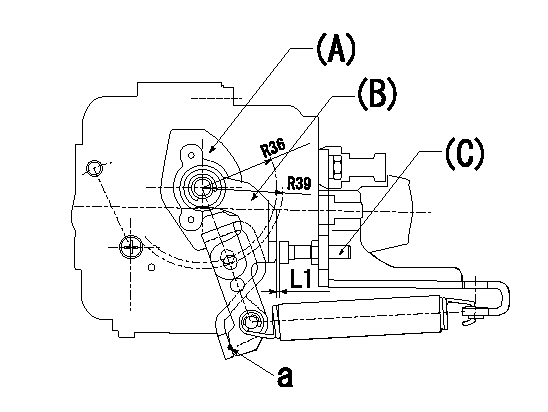
(a) Speed lever
(B) Accelerator lever
(C) Accelerator lever stopper bolt
1. Accelerator lever setting method
With the speed lever in the idling position, back off the accelerator lever stopper bolt L1 from where it contacts point a. (Back off 1+0.5 turns and set.)
----------
L1=1+0.5mm
----------
----------
L1=1+0.5mm
----------
Timing setting

(1)Pump vertical direction
(2)Position of timer's threaded hole at No 1 cylinder's beginning of injection
(3)-
(4)-
----------
----------
a=(60deg)
----------
----------
a=(60deg)
Information:
Illustration 10 g00562677
Long strings of text will crowd the screen. Keep the custom text as short as possible. If the screen is unreadable shorten the text. Touching the "Done" button returns you to the "Language Conversion" screen. Setup of the Communications
The next two windows are for the setup of communications. The screens are for the two Modbus RTU ports. Port 1 is RS-485 and Port 2 is RS-232C.The "Engine Setup (plc-Baud)" window allows a baud rate to be selected for the two ports. The"Engine Setup (plc-Address)" window is used for setting the external address.Note: Refer to sheet 22 of the MMS System Schematics for cable connections and information.Note: Refer to Systems Operation, "Signal Listing". This is a detailed list of all the Modbus output registers.
Illustration 11 g00594475
Illustration 12 g00594478
Auxiliary Options
Illustration 13 g00594454
Note: If your MMS has been customized at time of sale, some of these options may not be available.The user can configure 4 of the system's input. The terminal blocks for 2 RTDS are located in the MECP. The terminal blocks for 2 4-20mA transducers are also located in the MECP. The spare input may be used for any RTD or 4-20mA analog input.Touch the "Auxiliary Options" picture in order to configure the auxiliary input. Touch the "Auxiliary Options" picture in order to configure the auxiliary outputs. You are now on the "MMS Customation" screen."Edit Gauges" Screen
Touch the "Edit Gauges" button. Four auxiliary analog inputs are available. Each input may be added to the MMS display.Two of the inputs are for RTDS. The RTDS are set within a range of 0 °C (32.0 °F) to 150 °C (302.0 °F). The two remaining inputs are 4-20 mA. The inputs must have ranges that can be configured. This provides appropriate scaling for the numerical display. The ranges also provide appropriate scaling for the graphic display.
Illustration 14 g00594484
Auxiliary Temperature Input Setup
Touch the gauge in order to activate the specific "Auxiliary Temperature Gauge". The green check mark indicates that the gauge is activated.
Illustration 15 g00562687
Setup of the Auxiliary Analog Input
Touch the gauge in order to activate the specific "Auxiliary Analog Gauge". The green check mark indicates that the gauge is selected. Touch the "Gauge Range" box. This will display a numeric keypad. Enter the maximum value for the analog input. Touch the "OK" key. The scaling of the analog input start at zero.Touch the "UUU__XXXXXXXXX" box. This will display a keyboard. Type first 3 characters and then type a space. Type the label for the auxiliary analog input. Touch the "Enter" key in order to proceed.Customize the Auxiliary Labels
Note: The external keyboard will be required for this function.A keyboard with a PS/2 connection may be used. Plug the keyboard into the "keyboard" connection on the back of the PC.You are on the "MMS Customization" screen. Touch the "Edit Auxiliary Labels" button.
Illustration 16 g00594490
Labels for the Auxiliary Alarms
Note: The external keyboard will be required for this function. A keyboard with a PS/2 connection may be used. Plug the keyboard into the "keyboard" connection on the back of the PC.Four
Have questions with 101696-9893?
Group cross 101696-9893 ZEXEL
Nissan-Diesel
China
Nissan-Diesel
Nissan-Diesel
Nissan-Diesel
Nissan-Diesel
101696-9893
9 400 616 159
16713Z6963
INJECTION-PUMP ASSEMBLY
FE6TA
FE6TA